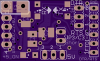
USB FTDI v4b Mini FT232RL
author: Heisenbug
2 layer board of 1.14 x 0.69 inches (28.8 x 17.5 mm)
Uploaded:
May 28, 2015
Shared:
June 16, 2015
Total Price:
$3.90
Tested & works great. Hand soldering is quite manageable, with the 0.65mm pitch IC pins of the FT232RL being the biggest challenge present.
A derivative of my v3 IC-only module. Same size/cost as v3.
The difference? This board is self-contained, and adds pads for a resettable fuse next to the USB header pads. (No, not specifically pads for a type-A USB male plug - you supply a cable and plug like this as I have done and attached via short pieces of 20-gauge wire, with good results. Uses standard USB order of +5v, Data(–), Data(+), GND / AKA the standard color coded red, white, green, black.)
Known issues:
* The data direction arrows point the wrong way relative to actual data flow… or you could say the TX and RX LEDs are in the wrong order due in part to a vague datasheet, but fixing the silkscreen arrows might be the easier fix.
* 6-pin FTDI-type header was designed for a female pin header and consequently has its drill size just a bit too small for standard square (male) pin headers - tested grinding down the pin corners to an octagonal shape, and it does indeed fit in there okay that way.
* Because of its double-sided nature - rather than riding on a single-sided carrier - it’s not very well suited for the slide-in bay on my Modul-Ar-duino. Perhaps double-sided foam tape plus a layer of rigid plastic over it may compensate for that.

