2.7-4.9V To 5V 250mA Mini Boost Converter
author: Eric
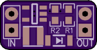
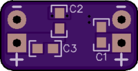
2 layer board of 0.59 x 0.30 inches (15.0 x 7.7 mm)
Uploaded:
February 28, 2014
Shared:
March 11, 2014
Total Price:
$0.85
Cost: $0.85 for three.
Description:
Miniature DC-DC boost converter for powering a microcontroller or sensor from battery power. This board will operate from 2.7-4.9V, so you can use two or three AA cells, one lithium cell such as a CR123A, 14520 or 18650, or one lithium-ion rechargeable.
With the feedback resistors specified, output is 5V, and the board can supply about 250mA. At 250mA load the components get warm, but temperatures are well within limits.
Bill of Materials:
- U1: Texas Instruments LMR62014XMF Boost Regulator (SOT-23-5)
- L1: Bourns SRN3015TA-100M 10µH Shielded Inductor (SMD 3mm x 3mm)
- D1: ON Semiconductor MBR0520LT1G 20V 0.5A Schottky Diode (SOD-123)
- C1, C3: Yageo CC0603KRX5R6BB475 4.7µF 10V 10% X7R Ceramic Capacitor (0603)
- C2: Samsung CL10B681KB8NNNC 680pF 50V 10% X7R Ceramic Capacitor (0603)
- R1: Stackpole RMCF0603FT10K2 10.2kΩ 1/10W 1% Resistor (0603)
- R2: Stackpole RMCF0603FT3K32 3.32kΩ 1/10W 1% Resistor (0603)
BoM Cost: $2.97
Notes:
Output voltage is set by resistors R1/R2. See the LMR62014XMF datasheet for details on setting other output voltages. Keep in mind that a large change will also require changes in inductor and capacitor values. You can safely change to 3.3V output from two AAs by changing R1 to 1.69kΩ, R2 to 1kΩ and C2 to 1500pF.
Output pads are 0.1-inch pitch and will accept standard pin headers. They are spaced 0.445 inch apart, input to output.

