Pocket Mouse Power Board v1.1
author: mousebitelabs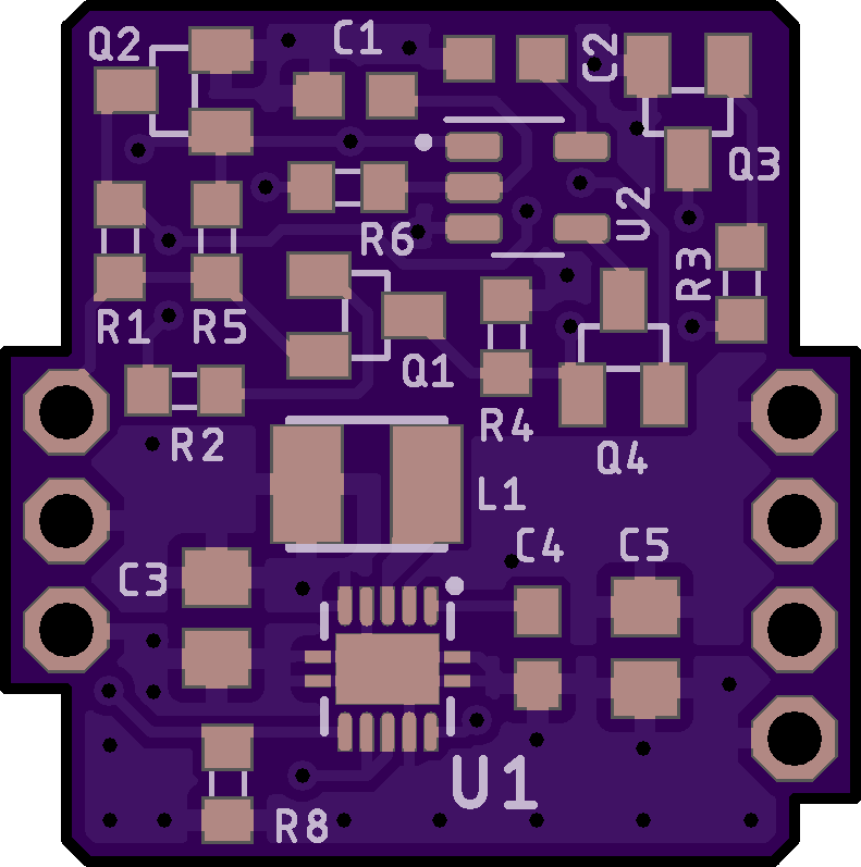

2 layer board of 0.79 x 0.79 inches (20.0 x 20.1 mm)
Uploaded:
March 18, 2023
Shared:
March 18, 2023
Total Price:
$3.10
Introduction
This is a power regulator board for my MGBC (Pocket Color) project. This should work perfectly fine on a regular Game Boy Color or Pocket, but I haven’t exhaustively tested it.
Disclaimer
Please keep in mind, I haven’t fully tested this power board, so you accept any and all risks associated with using this board. That being said, it’s similar to a lot of other replacement Game Boy power supplies out there, with a few distinct differences.
Features
Some features of this power board include:
- Changing the power switch to a “soft power switch,” meaning the main power of the Game Boy does not flow through the switch
- Improved efficiency over the OEM regulator
- Improves the audio output of the Game Boy
- Bootloop protection circuitry to prevent overdischarge of AAA batteries, and to allow the Game Boy to die gracefully instead of violently stuttering until the regulator gives up
Using with a GBC or MGB
If you wish to use this on a GBC/MGB, you must:
- Remove U5 from the Game Boy circuit board (the DC/DC converter board) and replace it with this one. Make sure you have a header pin populated for pin 2 on the socket!
- On the main Game Boy PCB, add a wire from pin 2 of the U5 socket to the node labelled SW1-VCC. This node connects to the power switch and F1, so you can choose either points.
- If you are soldering a wire to the fuse directly, MAKE SURE YOU CHOOSE THE CORRECT SIDE. It must be the side that’s directly connected to the power switch. A multimeter will not tell you which side of the fuse is which if you have the fuse on the board.
Also note this will only work with IPS modded systems. There are no LCD power rails.
Bill of Materials
Introduction
This is a power regulator board for my MGBC (Pocket Color) project. This should work perfectly fine on a regular Game Boy Color or Pocket, but I haven’t exhaustively tested it.
Disclaimer
Please keep in mind, I haven’t fully tested this power board, so you accept any and all risks associated with using this board. That being said, it’s similar to a lot of other replacement Game Boy power supplies out there, with a few distinct differences.
Features
Some features of this power board include:
- Changing the power switch to a “soft power switch,” meaning the main power of the Game Boy does not flow through the switch
- Improved efficiency over the OEM regulator
- Improves the audio output of the Game Boy
- Bootloop protection circuitry to prevent overdischarge of AAA batteries, and to allow the Game Boy to die gracefully instead of violently stuttering until the regulator gives up
Using with a GBC or MGB
If you wish to use this on a GBC/MGB, you must:
- Remove U5 from the Game Boy circuit board (the DC/DC converter board) and replace it with this one. Make sure you have a header pin populated for pin 2 on the socket!
- On the main Game Boy PCB, add a wire from pin 2 of the U5 socket to the node labelled SW1-VCC. This node connects to the power switch and F1, so you can choose either points.
- If you are soldering a wire to the fuse directly, MAKE SURE YOU CHOOSE THE CORRECT SIDE. It must be the side that’s directly connected to the power switch. A multimeter will not tell you which side of the fuse is which if you have the fuse on the board.
Also note this will only work with IPS modded systems. There are no LCD power rails.
