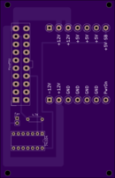
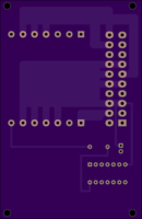
X68K_EZ_Pico_PSU
author: sergiovl
2 layer board of 2.41 x 3.71 inches (61.2 x 94.2 mm)
Uploaded:
January 07, 2019
Shared:
January 15, 2020
Total Price:
$44.60
SHARP X68000 PicoPSU Power Adapter
The goal of this project is to provide a simple-to-use adapter to power your SHARP 68000 ACE computer with a PicoPSU. The idea is to simply desolder the wire harness from your old (and presumably dead) X68K PSU, connect it to the screw terminals on this board, plug in a PicoPSU, and shove that back into the original PSU case.
Provided are Gerber files so you can make the boards. I use DirtyPCBs and fabricating these as prototype boards seems to do the trick (and inexpensively).
A few notes on the BOM (build of materials) included in the project:
(1) The selected ATX power molex has 2 plastic stand-offs on the bottom. The board does not account for those. Just shave them off with a knife.
(2) The ATX power molex needs a good push to get it through the board.
(3) The board has 2 7-pin header rows for the screw terminals. The last (unlabeled) pin on 1 of the header rows does nothing so the BOM specifies 1 6-pin heaer and 1 7-pin header. You can obviously do 2 7-pin headers if you want.
(4) The BOM includes a socket for the 74HC04 inverter. This is obviously optional. I just like sockets.
This project is provided with a GNU public license. Please copy, modify, and re-distribute. If you have suggestions, please let me know!

