Arduino Mini CAN-Bus
author: DF2RO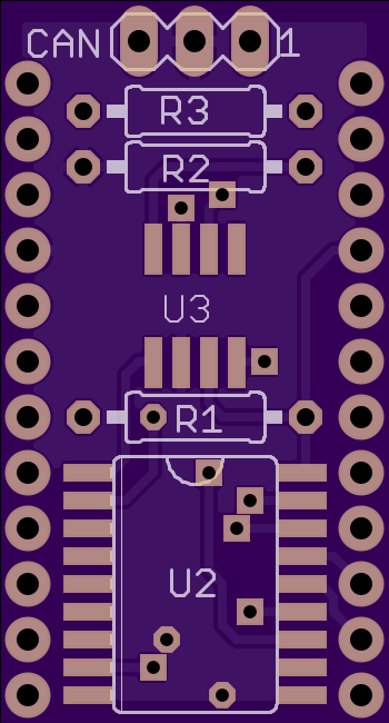
2 layer board of 0.70 x 1.30 inches (17.8 x 33.0 mm)
Uploaded:
April 17, 2016
Shared:
April 17, 2016
Total Price:
$4.50
This board can be soldered with pinheaders onto an Arduino Mini. It contains the MCP2515 CAN bus controller and the MCP2551 CAN tranceiver. The MCP2515 is connected to the hardware-SPI of the ATMega328p.
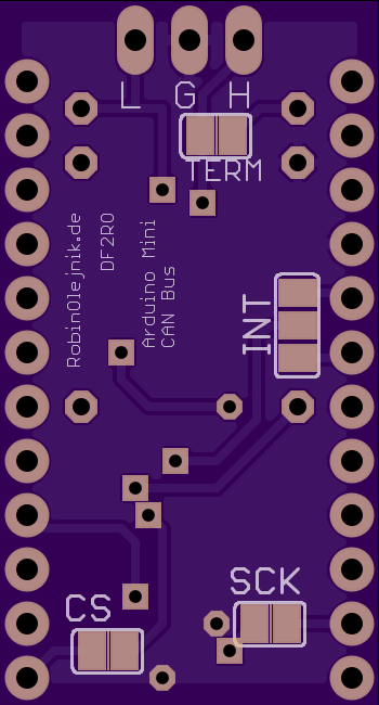
There are some jumpers:
| Jumper | Function |
|---|---|
| TERM | Connects an 120 Ohm bus termination to the CAN-lines. |
| SCK | Connects the ATMega328p’s clock output (Arduino pin 8/PB0/CLK0) to the MCP2515’s clock input. |
| CS | Connects the MCP2515’s chip select line to Arduino pin 10(PB2/SS). |
| INT | Connects the MCP2515’s interrupt line to either Arduino pin 2 (PD2/INT0) or Arduino pin 3 (PD3/INT1). |
If you want to use other pins you can solder a wire to the jumper pad
This project on my GitHub-page: https://github.com/robinolejnik/arduino_mini_can_bus
This board can be soldered with pinheaders onto an Arduino Mini. It contains the MCP2515 CAN bus controller and the MCP2551 CAN tranceiver. The MCP2515 is connected to the hardware-SPI of the ATMega328p.
There are some jumpers:
| Jumper | Function |
|---|---|
| TERM | Connects an 120 Ohm bus termination to the CAN-lines. |
| SCK | Connects the ATMega328p’s clock output (Arduino pin 8/PB0/CLK0) to the MCP2515’s clock input. |
| CS | Connects the MCP2515’s chip select line to Arduino pin 10(PB2/SS). |
| INT | Connects the MCP2515’s interrupt line to either Arduino pin 2 (PD2/INT0) or Arduino pin 3 (PD3/INT1). |
If you want to use other pins you can solder a wire to the jumper pad
This project on my GitHub-page: https://github.com/robinolejnik/arduino_mini_can_bus
