Overvoltage Protection Relay Driver (Rev G-TH)
author: Eric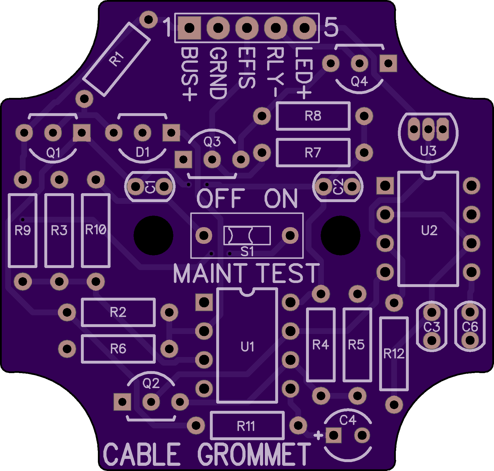
2 layer board of 1.71 x 1.63 inches (43.4 x 41.4 mm)
Uploaded:
May 08, 2025
Shared:
May 17, 2025
Total Price:
$13.90
Description: This board is as adaptation of the “OVM-14 Mk III Overvoltage Protection Module” designed by Robert L. Nuckolls III, as posted to the AeroElectric-List forum. The board provides overvoltage protection for the charging system in an Experimental category aircraft. It’s a relay driver instead of a crowbar; it opens relay(s) to interrupt the alternator field supply or the AC feed from a permanent magnet stator. It adds several features that are absent in the original version:
- EFIS alarm output. Sends a 10V (3mA limited) signal to an EFIS alarm input to notify the pilot that the module has tripped.
- Flashing OVP TRIP indicator LED output. 1.5Hz (20mA limited) output to flash an indicator LED on the instrument panel.
- PUSH ISOLATE switch. Allows pilot control of a permanent magnet stator feed (as in a Rotax 9-Series engine installation) and pilot reset of the module in the event of a nuisance trip.
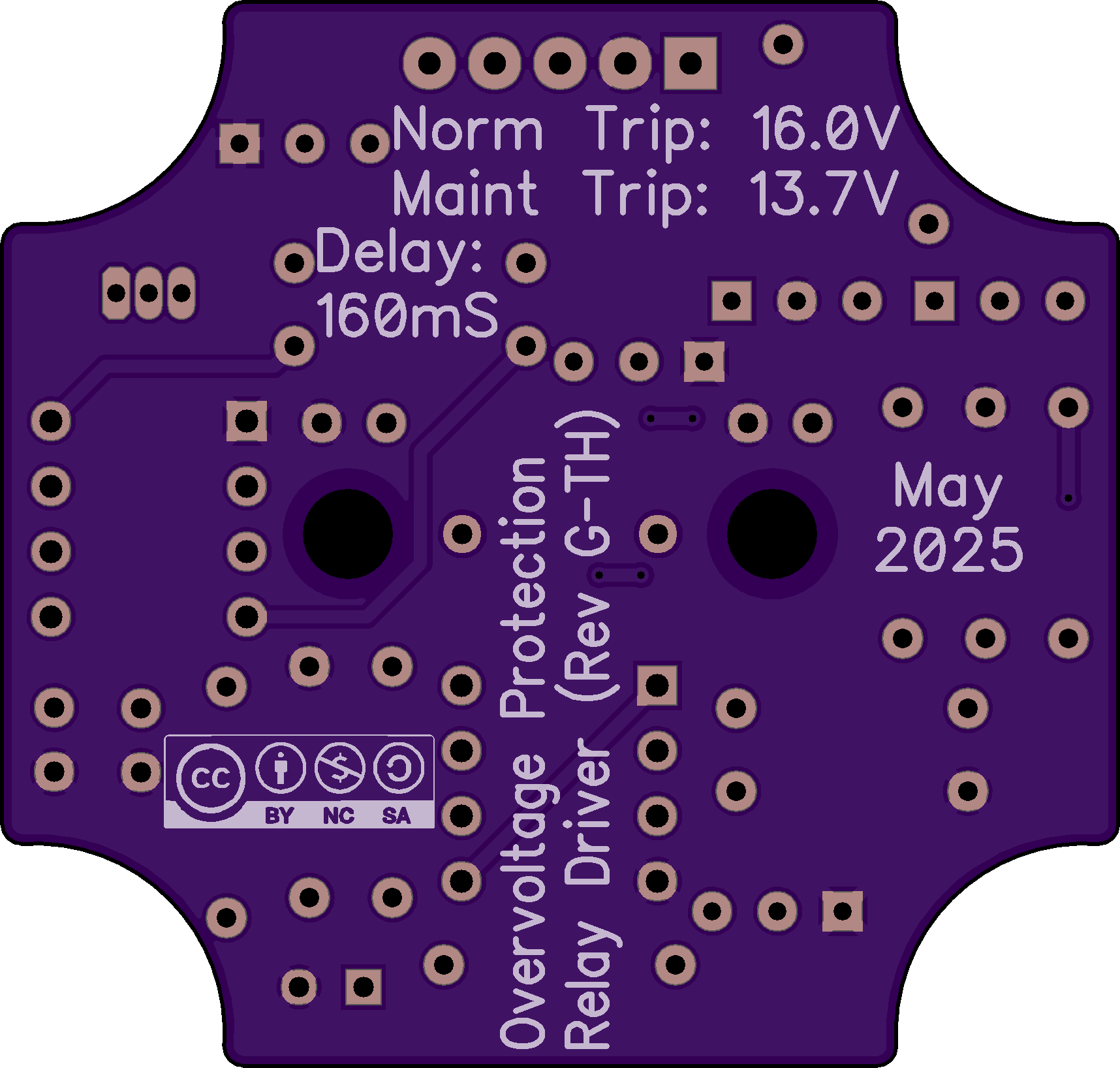
The nominal trip voltages are 16.0V in normal mode and 13.7V in maintenance test mode (both values subject to 1% resistor tolerance). The design is tested and working; see performance on the last two pages of the documentation PDF.
This project is intended for use in Experimental category aircraft only. Do NOT install it in a CAR Part 3 or FAR Part 23 certificated aircraft without FAA Field Approval.
BOM: Cost is ~$13 for the components to populate this board, plus builder’s choice of PUSH ISOLATE switch and indicator LED. Click for a Digi-Key saved list with required and suggested parts.
Download: Click here for a .ZIP archive containing full documentation in PDF format, DipTrace v5.1.0.3 CAD files and RS-274X Gerber files.
UPDATE - 29 May 2025 10:20AM PT: Files at the download link have been updated to correct an error in the values for R3 and R5. The circuit board layout is correct. R3 should be 1.02k and R5 should be 10.2k (these values were swapped in the original documentation). All other components are correct.
Description: This board is as adaptation of the “OVM-14 Mk III Overvoltage Protection Module” designed by Robert L. Nuckolls III, as posted to the AeroElectric-List forum. The board provides overvoltage protection for the charging system in an Experimental category aircraft. It’s a relay driver instead of a crowbar; it opens relay(s) to interrupt the alternator field supply or the AC feed from a permanent magnet stator. It adds several features that are absent in the original version:
- EFIS alarm output. Sends a 10V (3mA limited) signal to an EFIS alarm input to notify the pilot that the module has tripped.
- Flashing OVP TRIP indicator LED output. 1.5Hz (20mA limited) output to flash an indicator LED on the instrument panel.
- PUSH ISOLATE switch. Allows pilot control of a permanent magnet stator feed (as in a Rotax 9-Series engine installation) and pilot reset of the module in the event of a nuisance trip.
The nominal trip voltages are 16.0V in normal mode and 13.7V in maintenance test mode (both values subject to 1% resistor tolerance). The design is tested and working; see performance on the last two pages of the documentation PDF.
This project is intended for use in Experimental category aircraft only. Do NOT install it in a CAR Part 3 or FAR Part 23 certificated aircraft without FAA Field Approval.
BOM: Cost is ~$13 for the components to populate this board, plus builder’s choice of PUSH ISOLATE switch and indicator LED. Click for a Digi-Key saved list with required and suggested parts.
Download: Click here for a .ZIP archive containing full documentation in PDF format, DipTrace v5.1.0.3 CAD files and RS-274X Gerber files.
UPDATE - 29 May 2025 10:20AM PT: Files at the download link have been updated to correct an error in the values for R3 and R5. The circuit board layout is correct. R3 should be 1.02k and R5 should be 10.2k (these values were swapped in the original documentation). All other components are correct.
