Raspberry Pi JTAG Breakout
author: c2h5oh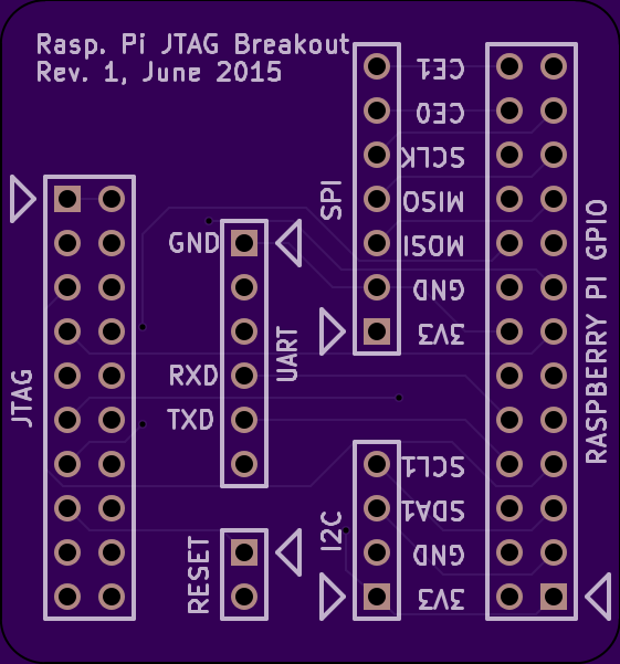
2 layer board of 1.40 x 1.50 inches (35.7 x 38.2 mm)
Uploaded:
May 30, 2015
Shared:
September 18, 2017
Total Price:
$10.55
Breaks out the Raspberry Pi (A or B, Rev. 2) GPIO header to an ARM 20 JTAG header. It will also work with Raspberry Pi A+ and B+, so long as you take care of the 26 to 40 pin conversion. I imagine it will also work with the Raspberry Pi 2, but I’ve not tried it out.
This is for debug access to the ARM core of the Broadcom chip, not the Video IV core.
I use an Olimex ARM-USB-OCD-H JTAG but this should work well enough with any standard ARM 20 JTAG debugger. Note that the DBGRQ and DBGACK pins are unconnected.
There is no pin on the GPIO header to initiate a system reset. Raspberry Pi boards have an unpopulated header (called P6 on Rev. 2 A and B boards, called Run on later boards). Solder in a 2 pin length of breakaway, and connect to the reset header on the JTAG breakout. Connect pin 1 to pin1, pin 2 to pin2. Then the JTAG adapter will be able to initiate a system reset.
The pins are not configured for JTAG by default at system reset. The pins are GPIO pins that have to be configured to alternate functions by software at boot time. For an example,see the armjtag project by David Welch.
The layout of the UART serial port breakout is the same as the Beaglebone Black, This is convenient for connecting USB to TTL serial adapters, such as the FTDI Friend or the FTDI Basic. Like the Beaglebone Black, pins 2, 3 and 6 of the UART header are unconnected.
