Modified Linkwitz Crossfeed
author: tomchuk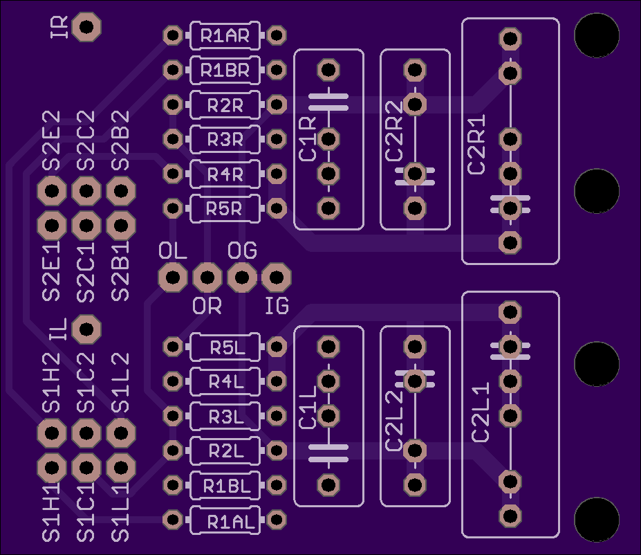
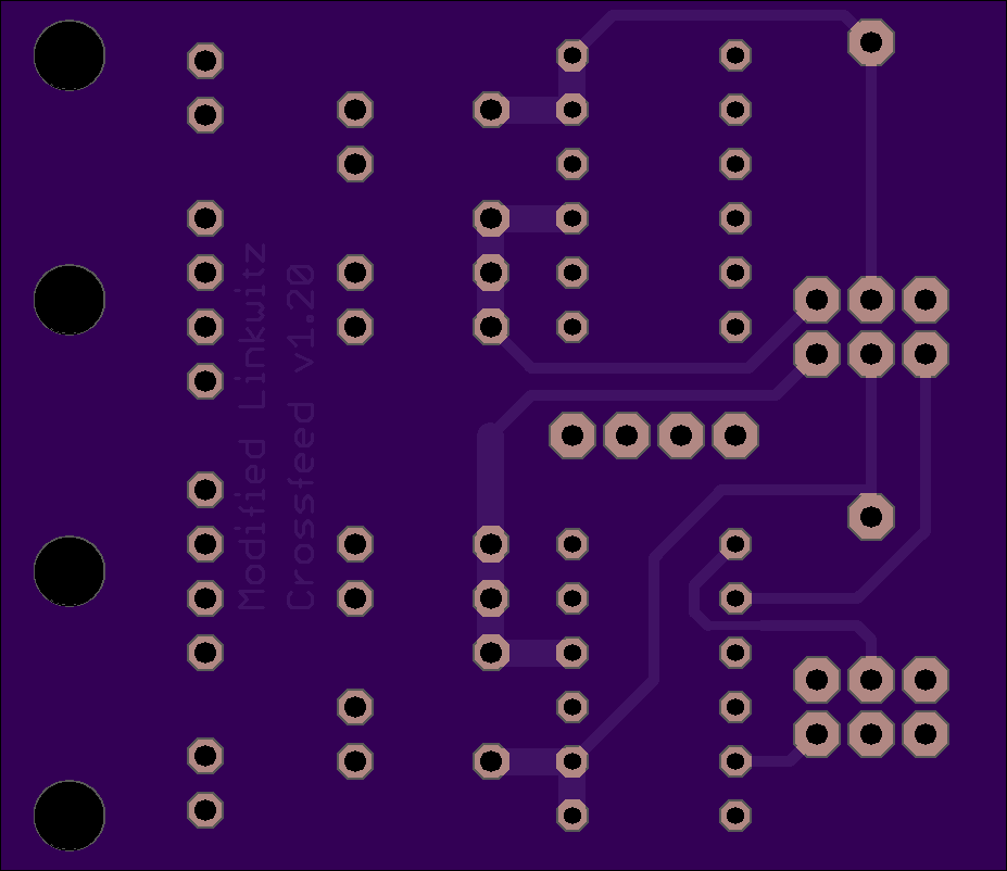
2 layer board of 1.85 x 1.60 inches (47.0 x 40.7 mm)
Uploaded:
September 07, 2018
Shared:
September 25, 2018
Total Price:
$14.80
This board was designed by Warren Young of Tangentsoft and uploaded here from the EAGLE files made available at his page on the Modified Linkwitz Crossfeed. A schematic with values for components is available here. This circuit is based on the work of Chu Moy, originally posted on HeadWize. That page has since disappeared from the internet, but here is a link to the page on The Wayback Machine for some added context.
I’ve built this project with the following parts from Mouser:
- 2 x 642-5246AB (DPDT Switches)
- 2 x 568-NYS367-2 (Red RCAs)
- 2 x 568-NYS367-0 (Black RCAs)
- 2 x 279-H82K0BYA (2K - R1A)
- 2 x 279-H81K5BYA (1.5K - R1B)
- 2 x 279-H81K0BYA (1K - R2)
- 2 x 279-H89K09BYA (9K09 - R3)
- 4 x 279-H83K32BYA (3k32 - R4 & R5)
- 2 x 667-ECW-F4223HL (0.22uF - C1)
- 2 x 667-ECW-F6124JL (0.12uf - C2)
Note the board accommodates C2(R|L)1 and C2(R|L)2 to allow using 0.1uF and 0.02uF capacitors in parallel, but the above 0.12uF caps can be used in the positions marked C2R1 and C2L1, omitting C2R2 and C2L2.
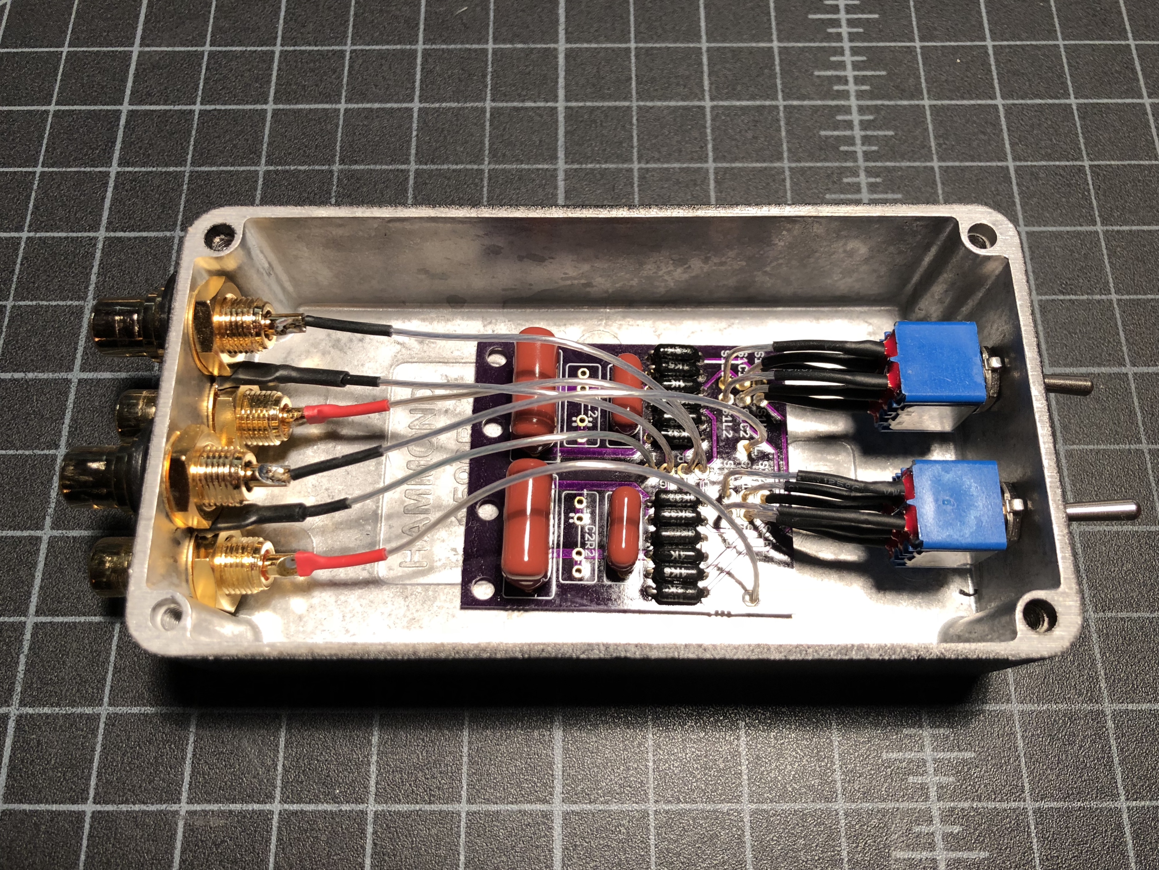
My completed build went into a Hammond 1590BBK (546-1590B-BK) - the RCAs will just fit on the short side of the box and leaves plenty of room for the switches up front and wiring up the PCB. A larger enclosure would make assembly much easier. Here are templates that can be used for drilling holes in the enclosure: Front Panel Switch Layout & Rear Panel RCA Layout. Note that the gray circles encompass the largest dimension of the square switch body and the largest dimension of the nut used to secure the RCA jacks. You should measure the components to select an appropriate drill size for the actual hole needed to mount the switches and jacks.
I used some heavy-duty double sided adhesive foam to secure the board in the box and some 7N silver plated OCC copper wire from eBay for hooking everything up.
This board was designed by Warren Young of Tangentsoft and uploaded here from the EAGLE files made available at his page on the Modified Linkwitz Crossfeed. A schematic with values for components is available here. This circuit is based on the work of Chu Moy, originally posted on HeadWize. That page has since disappeared from the internet, but here is a link to the page on The Wayback Machine for some added context.
I’ve built this project with the following parts from Mouser:
- 2 x 642-5246AB (DPDT Switches)
- 2 x 568-NYS367-2 (Red RCAs)
- 2 x 568-NYS367-0 (Black RCAs)
- 2 x 279-H82K0BYA (2K - R1A)
- 2 x 279-H81K5BYA (1.5K - R1B)
- 2 x 279-H81K0BYA (1K - R2)
- 2 x 279-H89K09BYA (9K09 - R3)
- 4 x 279-H83K32BYA (3k32 - R4 & R5)
- 2 x 667-ECW-F4223HL (0.22uF - C1)
- 2 x 667-ECW-F6124JL (0.12uf - C2)
Note the board accommodates C2(R|L)1 and C2(R|L)2 to allow using 0.1uF and 0.02uF capacitors in parallel, but the above 0.12uF caps can be used in the positions marked C2R1 and C2L1, omitting C2R2 and C2L2.
My completed build went into a Hammond 1590BBK (546-1590B-BK) - the RCAs will just fit on the short side of the box and leaves plenty of room for the switches up front and wiring up the PCB. A larger enclosure would make assembly much easier. Here are templates that can be used for drilling holes in the enclosure: Front Panel Switch Layout & Rear Panel RCA Layout. Note that the gray circles encompass the largest dimension of the square switch body and the largest dimension of the nut used to secure the RCA jacks. You should measure the components to select an appropriate drill size for the actual hole needed to mount the switches and jacks.
I used some heavy-duty double sided adhesive foam to secure the board in the box and some 7N silver plated OCC copper wire from eBay for hooking everything up.
