ATMegax8 TQFP to DIP 0805
author: Tomytronics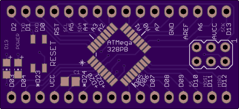

2 layer board of 1.67 x 0.76 inches (42.3 x 19.3 mm)
Uploaded:
July 26, 2018
Shared:
July 26, 2018
Total Price:
$6.30
You may be wondering why I made this when there are Arduino Nano or Arduino Mini Pro. It’s because I originally designed this to use ATMega328pB which came out a few years ago. Mini Pro and Nano do not have A6 or A7 in convenient place for breadboarding and on non ‘B’ version, they are only usable as analog input. The ‘B’ version also adds 2 GPIO pins that are not found on any Arduino board (official, clones, or offshoot variants) and to me this was a good reason to use ‘B’ version: 2 fully functioning analog pin that can use digitalRead or Write as well plus 2 digital pins. However Atmel and Microchip have not released this chip in DIP form for breadboarding, only in SMD packages so I needed to make a PCB to support this, have built in decoupling capacitors, built in ISP headers, built in power and D13 LED, built in crystal oscillator, and built in I2C resistor pads.
This board uses 0805 SMD resistors, capacitors, and LEDs. Please check my other uploaded design for slightly smaller 0603 parts if you prefer those instead.
- D20 and D21 is available only when using internal oscillator
- D22 is Reset pin, generally I don’t change fuse to enable D22 because it’s a pain to reprogram this without reset!
- D23 and D24 is available only on ‘PB’ variant. Otherwise they are GND and VCC respectively
- D25 and D26 shares A6 and A7 on ‘PB’ variants only; on non-‘PB’ variants, those are strictly analog input only
BOM:
the PCB
IC1: ATMegaxx8 TQFP-32, I suggest ‘328 for maximum flash memory, SRAM, and EEPROM
J1-J4: zero-ohm 0805 jumper resistor, see Note 1 and 2 below
C1, C2, C3: 0.1uF ceramic 0805 cap, see Note 1 below
C4, C5: ceramic 0805 cap, matching oscillator’s spec, see Note 2 below
Q1: crystal of desired speed, see Note 2 below
R1: 10k ohm 0805 resistor
R2, R3: 470 ohm 0805 resistor (may want to adjust this depending on LED spec and color, I went with 1k for red because it’s too darn bright!)
R4, R5: 4.7K 0805 resistor, see Note 3 below
1 0805 LED of your favorite color for power (ie green)
1 0805 LED of another color for D13 (ie amber/yellow)
2 16 pins header 0.1" spacing (2.54mm)
1 push button switch Panasonic EVQP2 series or similar switch with 4 leads SPST, 4.7mm x 3.5mm
Most 0805 SMD parts could theoretically have 0603 (resistors, capacitors, and LEDs) instead but you will have only about 0.3 mm on each side to solder on the pad.
Note 1: If you are not using PB variant of ATMega xx8 MPU, solder C2 capacitor plus J1 and J2 jumper. Otherwise do not populate these 3 parts to gain GPIO pin D23 and D24. This 2 pins are VCC and GND on non PB variants and can’t be used as GPIO.
Note 2: If you are using internal oscillator, solder jumper J3 and J4 to connect pins to header and gain GPIO pin D20 and D21. If you are using external oscillator, do not populate J3 and J4. Instead add Q1 such as Abracon ABM3 series SMD crystal. ABM3 requires either 18pF or 20pF capacitors, check first before buying. Populate C4 and C5 with correct 0805 cap. The crystal pad is tailored for ABM3 and may not quite fit other similar sized SMD crystal.
Note 3: pullup resistor for I2C (SCL and SDA) if needed. https://web.archive.org/web/20170115175107/http://www.nxp.com/documents/user_manual/UM10204.pdf to compute optimal resistor values but 4.7k are commonly used with 5v system.
