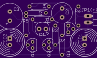
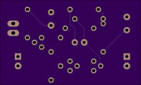
Halloween spooky eyes v2.0
author: Heisenbug
2 layer board of 1.49 x 0.90 inches (37.8 x 22.9 mm)
Uploaded:
September 22, 2020
Shared:
September 22, 2020
Total Price:
$6.70
(Almost) as-laid-out for a demonstration for Engineering club in fall 2019…timely upload, right? At least I beat Halloween this year! The version 2.1 layout from this same schematic, and the original perfboard prototype both v2.0 & v2.1 came from, work great on 3-9Vdc. PCB meant for soldering practice for club members - eventually. V2.0 is as-yet untested but fully expected to work, IF they’re not too heavy-handed with the soldering iron on these fine traces. Only changes from this to the tested & working v2.1 are thicker traces, a few components moved/shifted to optimize space for 3 [irregularly-placed] mounting holes, power plug is centered on the side and one hole/pad grounded, and the trace routing to match the few component moves. Same dimensions/cost and BOM.
ToUpdate - schematic & a v2.1 derivative link (eventually)
3 each 100K resistors (R1-R2-R3)
1 each 10K (R4), 4K7 (R5), 2K2 (R6), 100R (R7) - all can be 1/8w except this last one if running on >5v
22uF (C1), 47uF (C2), 100uF (C3)
2x 2n3904 (next to each other) + 1x 2n3906 (separate) - equivalents acceptable
2 LEDs that will look like the eyes you want, space onboard left for 10mm round jumbo type
Other values and ratings non-critical - try to get close to the values I used for good timing effect, and ratings should meet or exceed intended supply voltage - then it will simply work.
May be updating/sharing the version 2.1 derivative of this before the month is out. All holes populated - no-via design - an astable multivibrator and a third transistor as a driver means it’s simple enough that this design technique is … (pun-intentionally) … viable.

