DS_PLUS1.brd
author: brainwave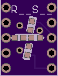
2 layer board of 0.38 x 0.50 inches (9.7 x 12.7 mm)
Uploaded:
December 10, 2016
Shared:
September 26, 2017
Total Price:
$0.95
Apollo uDSKY’s Registers Sign Digits
Working!
This board will allow a pretty good substitute for the non-existent compatible LED sign digits for an Apollo DSKY display. You will also need the DS_MASK.brd for each display if you want the displays to be more segment-ty? There are also some additional masking and diffusing techniques that can be done to make these look really good.
NOTES:
This is intended to be used with a 0.39" 10-pin LED displays such as LTS-4301G that were used on the uDSKY display.
The minus (-) are controlled by the standard G - Segment Pin 1 with 2 LEDs in series. The (+) is a combination of the “g1” and “g2” Segs and the vertical segments (some times referred to as “h” and “J”) which are connected to the “DP” pin 6. The Common pins are 8 and 3. Because both displays are two LEDs in series this should simplify non-MUX displays as well.
https://www.jameco.com/z/LTS-4301G-Lite-On-Electronics-Green-7-Segment-LED-Display_2227911.html
When selecting the SMT LEDs make sure you get them close to the brightness and color wavelength. For example , these LED displays have: 569 nm (green) and an avg. intensity = 2200 µCD @ If =10mA.
I will post some details on how to put these together. But basically, you need to diffuse the light or the viewing angle gets critical. I used a simple piece of scotch tape but hot melt glue may also work. A couple of baffles between the G and the vertical segments are also needed or when only (-) is displayed the other segments are still slightly visible. I used a couple scrap pieces of black wire insulation wedged between the segments to block this.
The parts placement is pretty simple, The anode of the first LED connects to the respective pin. The two LED’s cathodes and anodes for each segment are connected together. The cathodes of the 2nd LEDs connect to the common pins. If you forget one LED or get one in backwards… no light! The Eagle Files are at:
https://github.com/b-wave/uDSKY/tree/master/uDSKY%20Hardware/DSKY_DISP
Use two 0.1" 5-pin headers to hold the two boards together. Mount the header on top of this board (long pins go thru the board) Then put the mask board on top of the header. The boards are separated by the plastic header. Push the pins flush to the top MSK_Brd Pins 1, 6, 8, and 3 now have to be soldered on the bottom of this board. You can solder the mask board’s pins all in place if you want to - after you verify everything is working OK of course, there are no electrical connections.
