Raspberry Pi Zero Mono Audio Output (v1)
author: joem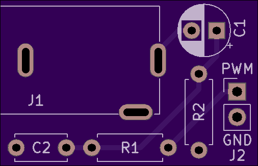
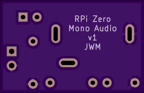
2 layer board of 1.01 x 0.65 inches (25.7 x 16.6 mm)
Uploaded:
April 20, 2019
Shared:
May 06, 2019
Total Price:
$3.25
[NOTE: This board hasn’t been tested yet. It’s simple enough that I’m fairly certain it’s OK, but in case it’s not, this is why. After I test it, I’ll remove this note.]
There are already some other RPi Zero audio output pcbs available, but this one was designed specifically with several goals in mind:
- mono
- through hole
- fits inside my RPi Zero case
- uses a PJ302M jack to mount it to the case
- decently documented
It’s based on a circuit from tinkernut though I’m not sure if they originated it (it’s just a passive filter, after all). See that tinkernut page for more info about setting up the RPi to work with it. And if that page ever disappears, feel free to google for something like “rpi zero pwm audio” since there are many articles about how to set that up. I used through-hole components because I didn’t have all the right parts in SMD. There are no mounting holes because it’s intended to be panel-mounted via the jack.
There is a project page on github for this with kicad source files, pdf schematics, gerbers, etc.

BOM:
- R1 = 270R
- R2 = 150R
- C1 = 10uF electrolytic, 2.5mm lead spacing
- C2 = 33nF ceramic, 5mm lead spacing (tinkernut’s page says “0.33uF” but other similar schematics say 33nF)
- J1 = PJ302M 3.5mm mono jack
- J2 = 1x2 pin header (I use right angle)
The lead spacing for the capacitors is not a strict requirement, since you can always bend the leads in or out a bit if you’re close. When shopping for the electrolytic cap, be aware of its size, especially if you’re going to be putting this in a tight space like I am.
[NOTE: This board hasn’t been tested yet. It’s simple enough that I’m fairly certain it’s OK, but in case it’s not, this is why. After I test it, I’ll remove this note.]
There are already some other RPi Zero audio output pcbs available, but this one was designed specifically with several goals in mind:
- mono
- through hole
- fits inside my RPi Zero case
- uses a PJ302M jack to mount it to the case
- decently documented
It’s based on a circuit from tinkernut though I’m not sure if they originated it (it’s just a passive filter, after all). See that tinkernut page for more info about setting up the RPi to work with it. And if that page ever disappears, feel free to google for something like “rpi zero pwm audio” since there are many articles about how to set that up. I used through-hole components because I didn’t have all the right parts in SMD. There are no mounting holes because it’s intended to be panel-mounted via the jack.
There is a project page on github for this with kicad source files, pdf schematics, gerbers, etc.
BOM:
- R1 = 270R
- R2 = 150R
- C1 = 10uF electrolytic, 2.5mm lead spacing
- C2 = 33nF ceramic, 5mm lead spacing (tinkernut’s page says “0.33uF” but other similar schematics say 33nF)
- J1 = PJ302M 3.5mm mono jack
- J2 = 1x2 pin header (I use right angle)
The lead spacing for the capacitors is not a strict requirement, since you can always bend the leads in or out a bit if you’re close. When shopping for the electrolytic cap, be aware of its size, especially if you’re going to be putting this in a tight space like I am.
