Staff v2
author: RobotHacker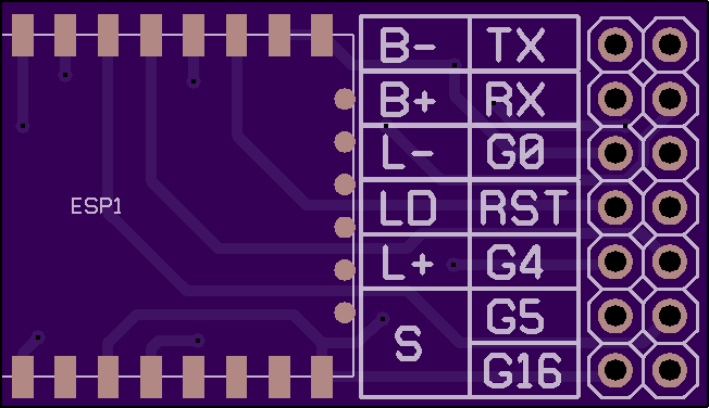
2 layer board of 1.30 x 0.75 inches (33.1 x 19.1 mm)
Uploaded:
May 30, 2017
Shared:
May 31, 2017
Total Price:
$4.90
Untested. Ordered 2017-05-31. Updates to follow.
Made with Autodesk Circuits (formerly 123D Circuits.) I am working on the documentation there then copying it here.
https://circuits.io/circuits/5009781-staff
My roommate wants to put a glowing crystal at the top of a staff. I threw together a circuit with a ESP8266, a WS2812 jewel module (7 addressable RGB LEDs,) a 14500 LiPo battery, and a LiPo charging module.
B- and B+ go to a LiPo battery (14500 in my case)
S goes to a switch to turn it on or off (short to turn on.) Battery can still be charged with it turned off.
L-, LD, and L+ go to a string of WS2812 LEDs. L- is GND, L+ is VCC, and LD is the data or signal line. I’m using a “jewel” module with 7 WS2812s on it.
TX, Rx, G0, and RST are for programming the ESP8266
G4, G5, and G16 are GPIOs from the ESP8266 for adding other components later.
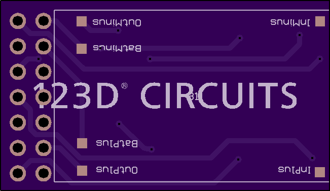
Update: I had PCBs made and it turned out ok. The pads for the lipo charger were a bit small (but worked) and the pads for the bottom of the ESP8266 were under the module a bit (but by shifting the module up just a bit I was able to make all the contacts work.
Still in progress.
Untested. Ordered 2017-05-31. Updates to follow.
Made with Autodesk Circuits (formerly 123D Circuits.) I am working on the documentation there then copying it here.
https://circuits.io/circuits/5009781-staff
My roommate wants to put a glowing crystal at the top of a staff. I threw together a circuit with a ESP8266, a WS2812 jewel module (7 addressable RGB LEDs,) a 14500 LiPo battery, and a LiPo charging module.
B- and B+ go to a LiPo battery (14500 in my case)
S goes to a switch to turn it on or off (short to turn on.) Battery can still be charged with it turned off.
L-, LD, and L+ go to a string of WS2812 LEDs. L- is GND, L+ is VCC, and LD is the data or signal line. I’m using a “jewel” module with 7 WS2812s on it.
TX, Rx, G0, and RST are for programming the ESP8266
G4, G5, and G16 are GPIOs from the ESP8266 for adding other components later.
Update: I had PCBs made and it turned out ok. The pads for the lipo charger were a bit small (but worked) and the pads for the bottom of the ESP8266 were under the module a bit (but by shifting the module up just a bit I was able to make all the contacts work.
Still in progress.
