Controlled Outlet V1.2
author: mathieusan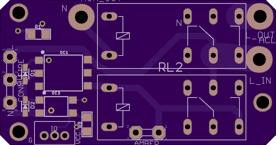
2 layer board of 2.12 x 1.12 inches (53.9 x 28.3 mm)
Uploaded:
June 10, 2020
Shared:
June 10, 2020
Total Price:
$11.80
Optocoupler to control a 120VAC 15A outlet from a smoke detector. Uses a standard hardwire smoke alarm which takes advantage of its 9VDC output “sensor line” sending high when there’s a fire. The board routes the 9V to an optocoupler. The isolated side consists of 2 non-latching relay configured as a latching circuit. If the board would to burn or lose power, the relay controlling the outlet is normally open.
The outlet is live during normal operation (when there is no fire). When triggered, the circuit will latches the relay to cut power to the outlet. The latching circuit is needed to ensure that any change in the smoke alarm trigger will not impact the state of the outlet (such as the smoke detector burning while still a fire is going on). If the board would burn as well, the relay would naturally stays opened.
The board has an additional output with pull down resistor to allow a generic microtrontroller to also pick up the fire alarm trigger and do some second level action (such as sending an email, or controlling something in a less critical fashion; home assistant status for example)
Relay 1: RT314615 Relay 2: RT214615 (also work if using RT314615) Optocouplers: MOC3023S and VOM617A most surface mounts are 1206; R1 is .25W One capacitor (220uF 25V) is in a surface mount can: EEE-1EA221P. This C1 capacitor is to allow a delay of about 200ms to avoid a false alarm.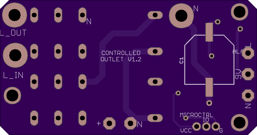
