CK's simple LED flasher for RC aircraft
author: Cereal_Killer
2 layer board of 0.79 x 0.39 inches (20.0 x 10.0 mm)
Uploaded:
April 12, 2015
Shared:
April 12, 2015
Total Price:
$1.55
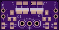
Very simple transistor based oscillator circuit I made from random parts out of my crap bin. Play with the parts values to change frequency. BOTH SIDES MUST MATCH or it will not flash! You can either wire in remote mounted LED’s (such as on alternating wings) or you can use 5mm LED’s directly on the back of the board if you had a use for that, they’ll mount directly in the vias.You can also use threw hole components with some interesting soldering, pretty much any NPN- bipolar transistor will work, you can also use a wide range of values for the R2/R3 and cap sets HOWEVER you need to maintain a similar ratio as found in my example or you can easily get to a flashing rate to fast to perceive. R1 and R4 don’t effect the flash rate.
- R1 & R4 are the set resistors for the brightness of each LED (these two may be mismatched, especially if using different color LED’s)
- R2 & R3 drain the cap’s
- Q1 and Q2 are any NPN BJT’s in an SOT-23 package
- CAP POLARITY IS CRITICAL! CAP’s + goes to LED-
- CAP pads are for 3216 metric (1206) size caps such as Kemet T series. Make sure you’re using minimum 25v rated caps, 10v tantalum caps are VERY common and WILL BLOW, check the datasheet for the letter voltage code if needed!
- Supply with raw 1s to 4s LiPO, can be powered directly from flight pack or even off a 5v pin from your flight controller.
My personal values:
- R1 & R4 = 220ohms
- R2 & R3 = 10K
- total of 44uF each side (using a pair of 22uF’s caps per side)
One final note, remember that on tantalum cap’s are normally marked with the line on + (what the SMD pads are marked for) so if you’re using threw hole cap’s you’ll probably need to ignore that (most threw hole caps have the line on -)

