2 transistor LED boost for 1.5V battery
author: datiLED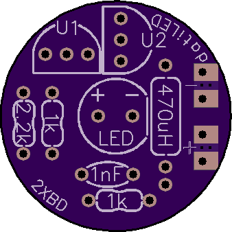
2 layer board of 0.68 x 0.68 inches (17.2 x 17.2 mm)
Uploaded:
January 29, 2020
Shared:
November 06, 2020
Total Price:
$2.25
A simple 2 transistor LED boost to drive a white LED using a 1.5V battery.
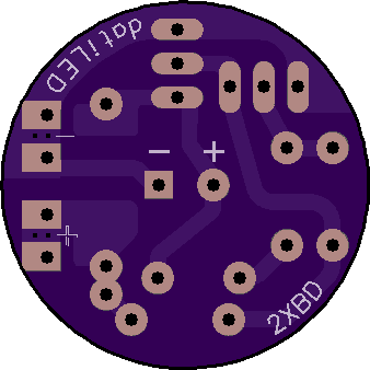
This simple circuit using common through-hole components will drive a white LED at approximately 7 - 10 lumens for many hours using a 1.5V alkaline battery. The power (rectangular pads) can be wired to a battery holder for a makeshift flashlight, or emergency power source. These are great for power outages!
Components mount on side of board with component outlines and designations. Place smaller components first, and work up to the taller components. After placing leads through the holes, bend them slightly to hold in place. Solder all of the components, watching for solder bridges. Clip the component leads close to the board . Attach leads to the rectangular pads and test for function. If the LED doesn’t light, verify component orientation for the LED and transistors. If you used different transistors than specified in the BOM, verify the pinout in the datasheet (which you should do before building).
BOM - Bill of materials for each module:
* (2) Fairchild PN2222a transistors. (Other NPN switching transistors with E,B,C pinout may work.)
* (2) 1k 1/8w resistors
* (1) 2.2k 1/8w resistor
* (1) 1nF (.001uF, 1000pF) ceramic capacitor
* (1) 470uH axial inductor (Values down to 220uH may also work with this circuit.)
* (1) 5mm white LED (3.2Vf or lower is best)
Designed for use with the 2oz. copper, 0.8mm board. However, you can get it made any way that you wish.
A simple 2 transistor LED boost to drive a white LED using a 1.5V battery.
This simple circuit using common through-hole components will drive a white LED at approximately 7 - 10 lumens for many hours using a 1.5V alkaline battery. The power (rectangular pads) can be wired to a battery holder for a makeshift flashlight, or emergency power source. These are great for power outages!
Components mount on side of board with component outlines and designations. Place smaller components first, and work up to the taller components. After placing leads through the holes, bend them slightly to hold in place. Solder all of the components, watching for solder bridges. Clip the component leads close to the board . Attach leads to the rectangular pads and test for function. If the LED doesn’t light, verify component orientation for the LED and transistors. If you used different transistors than specified in the BOM, verify the pinout in the datasheet (which you should do before building).
BOM - Bill of materials for each module:
* (2) Fairchild PN2222a transistors. (Other NPN switching transistors with E,B,C pinout may work.)
* (2) 1k 1/8w resistors
* (1) 2.2k 1/8w resistor
* (1) 1nF (.001uF, 1000pF) ceramic capacitor
* (1) 470uH axial inductor (Values down to 220uH may also work with this circuit.)
* (1) 5mm white LED (3.2Vf or lower is best)
Designed for use with the 2oz. copper, 0.8mm board. However, you can get it made any way that you wish.
