Tandy_100_102_200_DVI_twister.kicad_pcb
author: Brian_K_White

2 layer board of 0.28 x 2.01 inches (7.2 x 51.0 mm)
Uploaded:
July 07, 2019
Shared:
July 07, 2019
Total Price:
$2.80
The TRS-80 Disk/Video Interface for Models 100, 102, & 200, normally requires a special 40-wire ribbon cable where all of the wires are separated into pairs, and each pair is flipped over once along the way between the computer and the DVI. like this
Another way to achieve that same wire re-mapping, is to connect two standard pin headers back to back. It’s hard to explain verbally how this works, but just hold two connectors, male or female but both the same, two male or two female, up to each other, face to face, or back to back, with the pin1 marks on the same side (polarity notches on opposite sides), and look at where the pin1 marks end up. Each connectors pin1 mark ends up on the opposite connectors pin2.
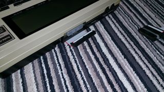
Because of this, the quickest and easiest way to make a working DVI cable is to butt two cables with female connectors up to each other, joined by a simple male-male “gender changer” 2x20 pin header. like this There are a couple problems with that though. The pins are exposed to shorting. The connector isn’t polarity-keyed, and so it’s possible to connect it upside down. When using with a Model 102 or 200, the pin header goes right into the computer, and then when you remove the cable, the pins can stay in the computer instead of coming out with the cable, and then they are difficult to get out of the computer simply because there is nothing to grab onto with your fingers.
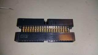
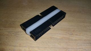
So this board just makes a male-male adapter that is electrically identical to the plain “gender changer” pin header, but with shrouds and polarity notches instead of bare pins. The shrouds protect the pins from shorting. The polarity notches protect against connecting the wrong way. And there is no problem with the pin header getting stuck in the computer.
Parts
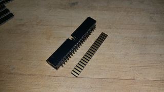
2 x shrouded male 2x20 pin header, through hole solder type
like this
Assembly
Solder the two pin headers back to back on the edges of this pcb, with the polarity notches on opposite sides, pin1 marks on the same side.
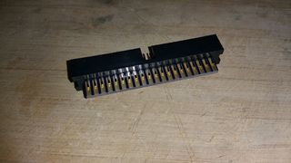
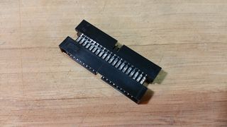
This is actually a silly project and isn’t really needed to make the adapter. You can solder the two connectors back to back to each other just by laying them on a flat surface, with the pins interleaved, with the connectors moved so one set of pins touches the other. This leaves plenty of space between pin-pairs so that bridging is not a problem. You just need a soldering iron tip that fits in the small gap between the two plastic parts. like this
This pcb just makes it easier. It’s easier to solder the two parts to a pcb like this than to solder them directly to each other.
Usage
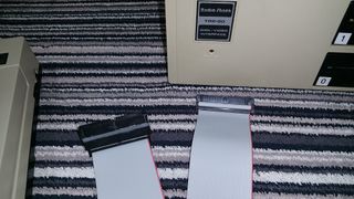
Start with a standard 40-wire ribbon cable 20 inches long with standard female IDC plugs w/polarity bumps and strain relief clips on both ends. Plug this adapter onto one end of the cable. Plug the other end into the Disk/Video Interface.
For Models 102 and 200
Plug the free end of the cabe (with the adapter on it) right in to the “System Bus” connector on the rear of the computer.

For Model 100
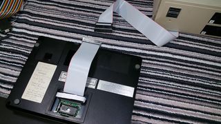
Make a short (8 inch) ribbon cable with a crimp-on 40-pin DIP plug on one end, and a standard female IDC plug on the other end. Plug the DIP plug into the system bus connector on the underside of the computer, so the free end of the short cable sticks out just past the rear of the computer. Plug the free end of the long cable (with the adapter on it) onto the free end of the short cable.
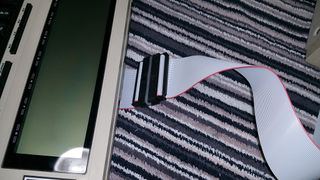
The TRS-80 Disk/Video Interface for Models 100, 102, & 200, normally requires a special 40-wire ribbon cable where all of the wires are separated into pairs, and each pair is flipped over once along the way between the computer and the DVI. like this
Another way to achieve that same wire re-mapping, is to connect two standard pin headers back to back. It’s hard to explain verbally how this works, but just hold two connectors, male or female but both the same, two male or two female, up to each other, face to face, or back to back, with the pin1 marks on the same side (polarity notches on opposite sides), and look at where the pin1 marks end up. Each connectors pin1 mark ends up on the opposite connectors pin2.
Because of this, the quickest and easiest way to make a working DVI cable is to butt two cables with female connectors up to each other, joined by a simple male-male “gender changer” 2x20 pin header. like this There are a couple problems with that though. The pins are exposed to shorting. The connector isn’t polarity-keyed, and so it’s possible to connect it upside down. When using with a Model 102 or 200, the pin header goes right into the computer, and then when you remove the cable, the pins can stay in the computer instead of coming out with the cable, and then they are difficult to get out of the computer simply because there is nothing to grab onto with your fingers.
So this board just makes a male-male adapter that is electrically identical to the plain “gender changer” pin header, but with shrouds and polarity notches instead of bare pins. The shrouds protect the pins from shorting. The polarity notches protect against connecting the wrong way. And there is no problem with the pin header getting stuck in the computer.
Parts
2 x shrouded male 2x20 pin header, through hole solder type
like this
Assembly
Solder the two pin headers back to back on the edges of this pcb, with the polarity notches on opposite sides, pin1 marks on the same side.
This is actually a silly project and isn’t really needed to make the adapter. You can solder the two connectors back to back to each other just by laying them on a flat surface, with the pins interleaved, with the connectors moved so one set of pins touches the other. This leaves plenty of space between pin-pairs so that bridging is not a problem. You just need a soldering iron tip that fits in the small gap between the two plastic parts. like this
This pcb just makes it easier. It’s easier to solder the two parts to a pcb like this than to solder them directly to each other.
Usage
Start with a standard 40-wire ribbon cable 20 inches long with standard female IDC plugs w/polarity bumps and strain relief clips on both ends. Plug this adapter onto one end of the cable. Plug the other end into the Disk/Video Interface.
For Models 102 and 200
Plug the free end of the cabe (with the adapter on it) right in to the “System Bus” connector on the rear of the computer.
For Model 100
Make a short (8 inch) ribbon cable with a crimp-on 40-pin DIP plug on one end, and a standard female IDC plug on the other end. Plug the DIP plug into the system bus connector on the underside of the computer, so the free end of the short cable sticks out just past the rear of the computer. Plug the free end of the long cable (with the adapter on it) onto the free end of the short cable.
