tool-head.kicad_pcb
author: alanlord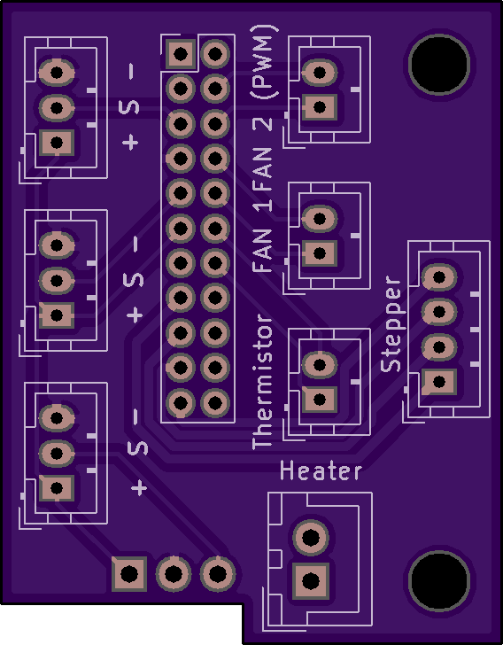
2 layer board of 1.14 x 1.46 inches (28.8 x 37.0 mm)
Uploaded:
March 19, 2018
Shared:
April 22, 2018
Total Price:
$8.25
This is a first try at making tool-heads for 3D printers easier to re-wire/change. You’ll need:
- 2 of these PCBs
- 6 x 3pin &
- 6 x 2 pin &
- 2 x 4 pin JST PH connectors,
- 2 x 2 pin XH connector for the cartridge heater &
- 2 x 22pin Molex Milli-grid.
Create your own cable using either the 22pin milli-grid crimp plug or they also make a ribbon IDC plug. I used the normal individual crimp pin plug. Wire the cable pin-to-pin, e.g. pin 1 at one end goes to pin 1 at the other.
Then cable each component to the PCB on the tool-head end and each connector to the relevant board connection on your printer control board(s).
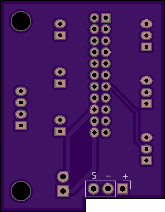
The bottom left sensor connector of the three (as you look at the top layout) is parallel connected to a three pin Dupont layout on the underside of the board - This allows me to plug in a Precision Piezo P20 probe detector.
NB: The three sensor connectors share a common +ve and -ve rail in the main wiring from the Molex connector - only the signal pins are independent. This might be an issue if you use mechanical (2 pin) end-stop switches rather than 3 pin optical devices. The reason why there are three sensor connectors was to be flexible for applications. It might be the case you need a probe and a MIN and MAX stop sensor. Of course you do not need to use all three. In my current CoreXY I use one for X Min and one for my Precision Piezo probe.
This is a first try at making tool-heads for 3D printers easier to re-wire/change. You’ll need:
- 2 of these PCBs
- 6 x 3pin &
- 6 x 2 pin &
- 2 x 4 pin JST PH connectors,
- 2 x 2 pin XH connector for the cartridge heater &
- 2 x 22pin Molex Milli-grid.
Create your own cable using either the 22pin milli-grid crimp plug or they also make a ribbon IDC plug. I used the normal individual crimp pin plug. Wire the cable pin-to-pin, e.g. pin 1 at one end goes to pin 1 at the other.
Then cable each component to the PCB on the tool-head end and each connector to the relevant board connection on your printer control board(s).
The bottom left sensor connector of the three (as you look at the top layout) is parallel connected to a three pin Dupont layout on the underside of the board - This allows me to plug in a Precision Piezo P20 probe detector.
NB: The three sensor connectors share a common +ve and -ve rail in the main wiring from the Molex connector - only the signal pins are independent. This might be an issue if you use mechanical (2 pin) end-stop switches rather than 3 pin optical devices. The reason why there are three sensor connectors was to be flexible for applications. It might be the case you need a probe and a MIN and MAX stop sensor. Of course you do not need to use all three. In my current CoreXY I use one for X Min and one for my Precision Piezo probe.
