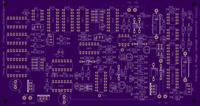
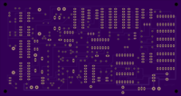
Tony Wood Side VIC_Circuit_Production_Eagle-5.10.0_&_Gerber_Files
author: SecureSupplies
2 layer board of 6.78 x 3.59 inches (172.1 x 91.1 mm)
Uploaded:
July 06, 2018
Shared:
July 07, 2018
Total Price:
$121.50
Tony Wood Side VIC_Circuit_Production_Eagle-5.10.0&Gerber_Files
experiences with circuit suggestions
clipped fom post to another forum tony =I’ve just finished re-designing the complete VIC circuit and I’m going to have some PCB professionally manufactured. If I can get enough potential buyers, I will be selling these boards complete with all components installed and placed into a 7.5"x 4.25"x2.25" enclosure with all appropriate controls on the panel. This VIC circuit will include the following circuits all on one board: “Variable Pulse Frequency Generator”, “Gated Pulse Frequency Generator”, “Phase Lock Circuit”, “Resonant Scanning Circuit”, Resonant Feedback", and “Cell Driver Circuit”. The sale price will be $300 + S&H. If you would like more info please email me at [email protected]
I’m also selling bare Professionally made Printed Circuit Boards of the 8XA Circuit, which measure 4.6"x2.3" for $35.00 +$5.00 S&H.
To purchase the 8XA Circuit PCB follow this link to my website http://www.globalkast.com/products.htm Thanks, Tony Woodside
Do you think the secondary coil is supposed to be center tapped? thats correct…the reason I used the center tap is because the VIC Trans acts like center tap trans. In Stan’s trans you want your reference point to be between the Secondary and L2 (negative) choke and you should see this same effect.
Did you build everything just from don’s schematics or did you take into account everything that was in the pictures as well? it seems like some things were left out of the schematics anyway, it sounds awesome and once I get some more info,
I’ve tested the circuit using my VIC transformer and I substituted my single tube cell for a real 10nF capacitor to make sure the circuit was locking in on resonance at the calculated frequency. The circuit would lock on and the voltage across the capacitor was measured at over 1700v with a 12v pulsed input. So the circuit work as Stan says it does. , I’ve built everything based on the actual circuits from the images. I did refer to the schematic that Don sent out and I have found a few errors with the schematic. The circuit does find and lock in to the resonant frequency of the LC circuit. It works very well. I actually built this circuit as my final project for my Electronics class and my electronics professor was very impressed with how it all worked and of course I got a grade of 100 on it..
The function of the circuit is explained in the PDF file “The Birth of New Technology” starting on page 44, Memo WFC 422 DA. Also refer to Patent #92007861 for the basic schematic.

