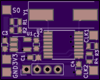
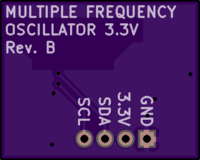
Multi Frequency Oscillator rev. B
author: skum
2 layer board of 0.75 x 0.61 inches (19.2 x 15.4 mm)
Uploaded:
September 17, 2018
Shared:
September 17, 2018
Total Price:
$2.25
Idea taken from this thread but since I sometimes needed to switch two frequencies, I made this. Example where it is usable, is when a PSX/PS1/PSone switches between NTSC and PAL, it needs to switch both the carrier frequency of the video signal AND the clock frequency to the GPU/DAC to have a proper video signal, that doesn’t go black and white and so on. This version is functionally identical to initial revision, but 4,3mm more narrow.
Parts list
- U1 1.8V LDO Regulator, here a TPS78218 (Mouser P/N: 595-TPS78218DDCT)
- U2 Texas Instruments CDCE925 (Mouser P/N: 595-CDCE925PWR)
- C1 1uF 0603 SMD capacitor
- C2 1uF 0603 SMD capacitor
- C3 1uF 0603 SMD capacitor
- C4 1uF 0603 SMD capacitor
- R1 10K 0603 SMD resistor
- R2 10K 0603 SMD resistor
- R3 18R 0603 SMD resistor (or whatever needed to accomodate signal to the circuit)
- R4 18R 0603 SMD resistor (or whatever needed to accomodate signal to the circuit)
- Y1 27MHz crystal (Mouser P/N: 774-ATS270BSM-1E or the shallower 815-ABLS3-27MD4YFT)
Use 0.8 mm substrate for the most shallow profile.
Note that Y2 and Y4 are parallel coupled, same with Y3 and Y5. Thus if programming with TI’s ClockPro software, Y4 must be tri-stated when Y2 output is on, and Y5 should be tri-stated when Y3 is on. Of course also vice-versa.
More info here

