Disco Splits - MidI thru/splitter
author: Lightaces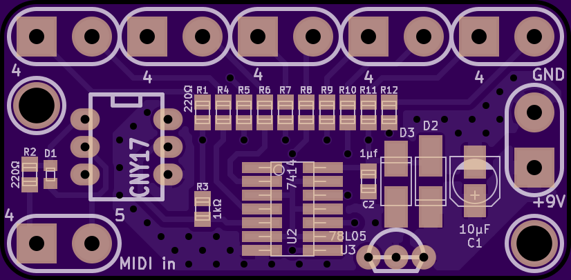
2 layer board of 2.07 x 1.02 inches (52.4 x 25.8 mm)
Uploaded:
September 23, 2014
Shared:
September 23, 2014
Total Price:
$10.45
This is a very simple MIDI splitter box. Sometimes, when you run too many MIDI devices in a chain, you can get errors caused by the slew rate of up to 16 opto-couplers. This Project fixes that by using a Schmitt trigger buffer to clean up the data transitions, and running the data to different units in parallel, instead of strictly in series.
It works best using a 74HC14, or 74HCT14. I’m told you could also use a 74HC04 or 74HCT04, but the Schmitt trigger in the 14 is the main reason for the project, at least for me. The resistors and C2 are all 0805 packages, the 74HC14 is a narrow SOIC14. D1 is the only really difficult part, as it is a tiny package (SOD523). D1 is a 4148, D2 and D 3 are GF1A. R3 is 1kOhm, but all the other resistors are 220 Ohm. The LM78L05 is a TO92 package, because I had it on hand, and similarly, the opto is a DIP6 CNY17. This board is tested, and it worked when I built it.
If you want an “MIDI active” LED, you can simply wire an LED to one of the outputs (do not wire it to a MIDI connector as well - it can’t drive both). The cathode of the LED is wired to pin 5 (the round pad).
Also, don’t forget to wire pin 2 of the OUTPUT MIDI connectors (the center of the 5 pins) to ground. This is for the MIDI cable’s shield. On no account should pin 2 of the input connector be wired to anything.
