teensysee
author: autotelic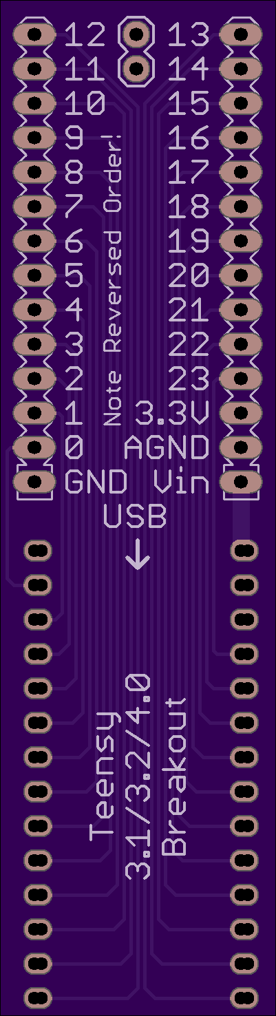
2 layer board of 0.80 x 2.95 inches (20.4 x 75.0 mm)
Uploaded:
September 24, 2019
Shared:
October 06, 2019
Total Price:
$11.80
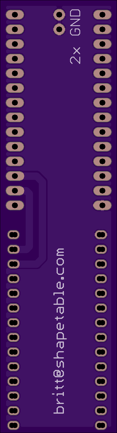
Stackable breakout debug board for Teensy 3.1/3.2/4.0. Debug header exits at rear. Different Teensy-based projects have different amounts of space around the Teensy itself. Usually the rear of the Teensy is not blocked, since that is where the USB cable connects. TeensySee breaks out the main Teensy signals and provides them on 2x 0.1" headers, suitable for connecting logic analyzer and oscilloscope probes. In addition to the Teensy GND and AGND pins, 2 additional GND pins are provided at the 2-pin header between pins 11/12 and 13/14.
Note the double drills for each of the holes in the Teensy footprint. This is intentional. The board can be assembled for either the more common larger square-pin 0.1" headers OR the smaller round machine-pin header and a machine-pin socket. For the square-pin version, just load stackable (Arduino-style) connectors. For the machine-pin version, load a female machine-pin strip on one side and a male machine-pin strip on the other. I find it helpful to use 2 additional strips plugged at a right angle into each of the strips being soldered. This will hold them at the right spacing and angle. BE SURE TO ORIENT THEM IN THE DOUBLE HOLES THE RIGHT WAY – e.g., both socket strips to the left drills, and both pin strips to the right drills.
