PWM Fan Controller
author: kevinaceman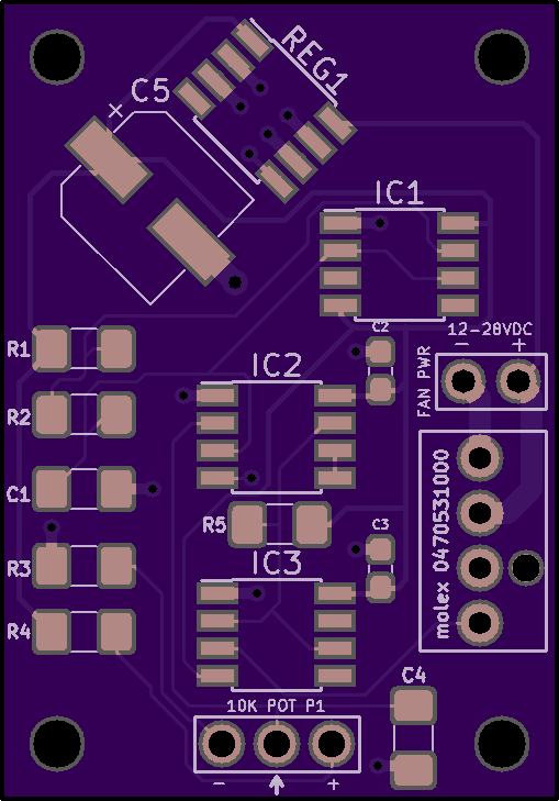

2 layer board of 1.02 x 1.46 inches (25.9 x 37.0 mm)
Uploaded:
December 26, 2018
Shared:
December 26, 2018
Total Price:
$7.40
The schematic for this board was principally derived from post #25 by overclockers.com forum member “bing”, see http://www.overclockers.com/forums/showthread.php/641111-Building-PWM-Controller-for-4-wires-PWM-fan?s=ec44cf65984bfd7d7fd8d02407c8e1cc
This board aims to package the circuit into a small footprint using larger, easy to solder SMT packages. In summary, this circuit generates a discrete ~25 kHz square wave, and the duty cycle can be adjusted from 0 to 100% using a potentiometer of your choosing. The board contains a 5 volt regulator for the PWM logic, which is capable of running up to 30 volts. If you wish to use a higher voltage fan (48 volts), you may change the regulator to one with a higher input operating voltage. The logic is 12 volt compatible, but C5 would have to be changed to accomodate the higher voltage. It is currently specified to be a 10 volt capacitor as the logic runs on 5 volts in the configuration seen here.
The bill of materials, Gerber and KiCad files, and images of the first test board being evaluated are available here:
https://drive.google.com/open?id=1aKoPmhgVg5st1XiLXO8zLtI2ykRgVHOm
Disclaimer: No guarantees expressed or implied. The information presented here is for educational use. You are responsible for safely and correctly assembling this open source project. I am not liable for any damages or injures to equipment or persons as a result of improper handling procedures, incorrect assembly, or misuse. Please ensure you exercise proper safety precautions as defined by NFPA 70 and NFPA 70E when assembling and using electronics.
By Kevin Aghaei
