DC High Side Switch v1.1 (DMG6602)
author: OolutionTech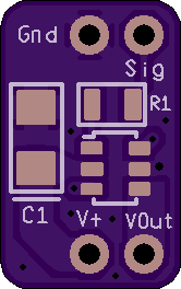
2 layer board of 0.33 x 0.53 inches (8.4 x 13.4 mm)
Uploaded:
January 19, 2021
Shared:
January 24, 2021
Total Price:
$0.85
DC High Side Switch v1.1 - Should use 2oz Board
Uses low voltage NMOS to switch higher voltage PMOS so this is microcontroller friendly
30V 2.3A Max (higher depending on gate voltage and maybe small heatsink plastered to MOSFET package) Uses DMG6602SVTQ-7 P&N MOSFET in TSOT26-6 Package for switching
C1 = 10uF Tantalum Capacitor 1005 (2512)
IC1 = DMG6602SVTQ-7 (P&N MOSFET TSOT26-6)
R1 = 150 Ohm Resistor 0805
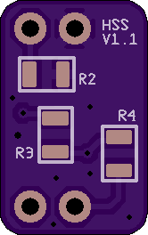
R2 = 100k Ohm Resistor 0805
R3 = 150 Ohm Resistor 0805
R4 = 33k Ohm Resistor 0805
R1 & R3 are protection (can go as low as 20 ohm). R2 is a pulldown to guarantee circuit is off if signal is left floating (keep high to reduce current draw and keep signal speed high). R4 limits amount of current flowing through NMOS (keep high to reduce current draw and keep signal speed high). Adjust resistors as needed. C1 is optional but is highly suggested to prevent voltage fluctuations especially if used in PWM application. Connectors are 2.54mm breadboard friendly. PWM speed is limited by R1 and gate capacitance. Use gate driver on signal pin if PWM speed exceeds microcontroller’s IO current/voltage capability.
DC High Side Switch v1.1 - Should use 2oz Board
Uses low voltage NMOS to switch higher voltage PMOS so this is microcontroller friendly
30V 2.3A Max (higher depending on gate voltage and maybe small heatsink plastered to MOSFET package) Uses DMG6602SVTQ-7 P&N MOSFET in TSOT26-6 Package for switching
C1 = 10uF Tantalum Capacitor 1005 (2512)
IC1 = DMG6602SVTQ-7 (P&N MOSFET TSOT26-6)
R1 = 150 Ohm Resistor 0805
R2 = 100k Ohm Resistor 0805
R3 = 150 Ohm Resistor 0805
R4 = 33k Ohm Resistor 0805
R1 & R3 are protection (can go as low as 20 ohm). R2 is a pulldown to guarantee circuit is off if signal is left floating (keep high to reduce current draw and keep signal speed high). R4 limits amount of current flowing through NMOS (keep high to reduce current draw and keep signal speed high). Adjust resistors as needed. C1 is optional but is highly suggested to prevent voltage fluctuations especially if used in PWM application. Connectors are 2.54mm breadboard friendly. PWM speed is limited by R1 and gate capacitance. Use gate driver on signal pin if PWM speed exceeds microcontroller’s IO current/voltage capability.
