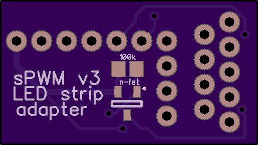
sPWM v3 LED strip adapter
author: HolyFockBoxMods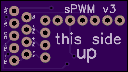
2 layer board of 1.03 x 0.58 inches (26.2 x 14.8 mm)
Uploaded:
January 05, 2018
Shared:
January 05, 2018
Total Price:
$2.95
v0.1 - any feedback appreciated!!!
Edit: after several tests, it’s proofed to work fine
The sPWM v3’s LED pin is only capable of 15mA, so here’s a little PCB to add LED strip support. This PCB is intended to be used with 2 tactile switches as up / down buttons.
additional components:
- SOT-23 n-fet (i.e. AO 3422 or similar)
- 100k 0805 resistor (optional, only if MosMax' supplemental board or a master on/off switch is used)
- 2.54 pitch male connection headers (https://www.digikey.com/product-detail/en/harwin-inc/M20-9990446/952-2266-ND/3728230)
Wiring:
- “LEDs+”: LED strip’s positive
- “LEDs-”: LED strip’s negative
- “GND”: wires coming from up/down tac switches, switch and black VM wire
- “VMr”: red VM wire
- “VMy”: yellow VM wire
- “Vin”: battery+
- “Pot+”: wire from UP tac switch
- “Pot-”: wire from DOWN tac switch
- “Sw”: wire from switch
- use standard 2.54mm pitch headers to solder on the sPWM v3 by Voltrove (Mosfet facing up!)
- if using an LED instead of a voltmeter, solder LED+ to VMr, leave VMy free
- all wires are routed to the left
adds a slightly bigger footprint to the v3
Links:
-MosMax sPWM v3 supplemental board
