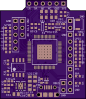
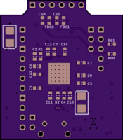
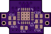
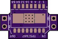
2 layer board of 2.51 x 0.81 inches (63.7 x 20.5 mm)
Uploaded:
July 05, 2020
Shared:
July 13, 2020
Total Price:
$10.10
(gerber pack version: v1.0 20200705-0105)
Link to Hackaday project: <https://hackaday.io/project/173730-stm32g473cxt6-breadboardable-minimal-system>
This is a minimal system of STM32G473CxT6 MCU — all 48 pins, plus +5V power input, are exposed on a compact breadboard-compatible footprint …
(gerber pack version: v1.0 20200705-0105)
Link to Hackaday project: https://hackaday.io/project/173730-stm32g473cxt6-breadboardable-minimal-system
This is a minimal system of STM32G473CxT6 MCU — all 48 pins, plus +5V power input, are exposed on a compact breadboard-compatible footprint (800 x 2500 mils). Although it looks like a glorified QFP-to-DIP adapter board, it actually has a few features that greatly improve Quality of Life while not adding too much to cost:
- Micro-USB connector
- VBUS can be used to power the board
- Data lines are connected to MCU
- Flexible power
- Feed either VBUS or external 5V to on-board 3.3V LDO
- TVS + reverse-polarity protection on +5V
- Alternatively use external 3.3V and forget about 5V
- Cortex Debug Connector (2x5 keyed shrouded 1.27mm pitch)
- HSE (high-speed external oscillator)
- Footprint for 4-pad SMD crystal + load capacitors
- Alternatively free up the pins for GPIO
- On-board reset button
BOOT0 handling
- 47k pull-down + 1k pull-up (through jumper)
- Since
BOOT0 is multiplexed with PB8 on this package, this setup avoids accidentally back-driving external circuitry.
- Power LED (+3.3V) and “Blinky” LED (
PC13)
- Silkscreen on both side clearly indicating pinout
- Headers can be soldered on both sides, although back-side male headers are preferred for breadboard compatibility
Show full description
(gerber pack version: v1.0 20200705-0105)
Link to Hackaday project: <https://hackaday.io/project/173730-stm32g473cxt6-breadboardable-minimal-system>
This is a minimal system of STM32G473CxT6 MCU — all 48 pins, plus +5V power input, are exposed on a compact breadboard-compatible footprint …
(gerber pack version: v1.0 20200705-0105)
Link to Hackaday project: https://hackaday.io/project/173730-stm32g473cxt6-breadboardable-minimal-system
This is a minimal system of STM32G473CxT6 MCU — all 48 pins, plus +5V power input, are exposed on a compact breadboard-compatible footprint (800 x 2500 mils). Although it looks like a glorified QFP-to-DIP adapter board, it actually has a few features that greatly improve Quality of Life while not adding too much to cost:
- Micro-USB connector
- VBUS can be used to power the board
- Data lines are connected to MCU
- Flexible power
- Feed either VBUS or external 5V to on-board 3.3V LDO
- TVS + reverse-polarity protection on +5V
- Alternatively use external 3.3V and forget about 5V
- Cortex Debug Connector (2x5 keyed shrouded 1.27mm pitch)
- HSE (high-speed external oscillator)
- Footprint for 4-pad SMD crystal + load capacitors
- Alternatively free up the pins for GPIO
- On-board reset button
BOOT0 handling
- 47k pull-down + 1k pull-up (through jumper)
- Since
BOOT0 is multiplexed with PB8 on this package, this setup avoids accidentally back-driving external circuitry.
- Power LED (+3.3V) and “Blinky” LED (
PC13)
- Silkscreen on both side clearly indicating pinout
- Headers can be soldered on both sides, although back-side male headers are preferred for breadboard compatibility
Show full description


