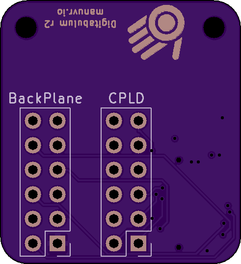
Digitabulum-r2-Backplane
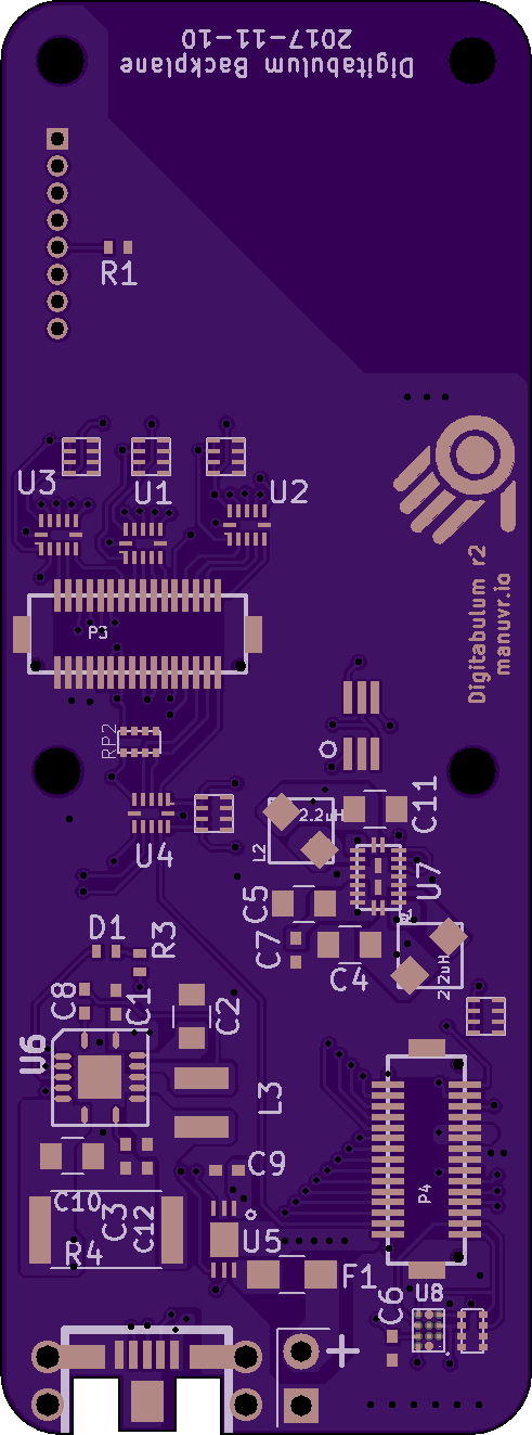
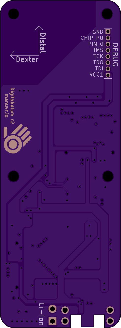
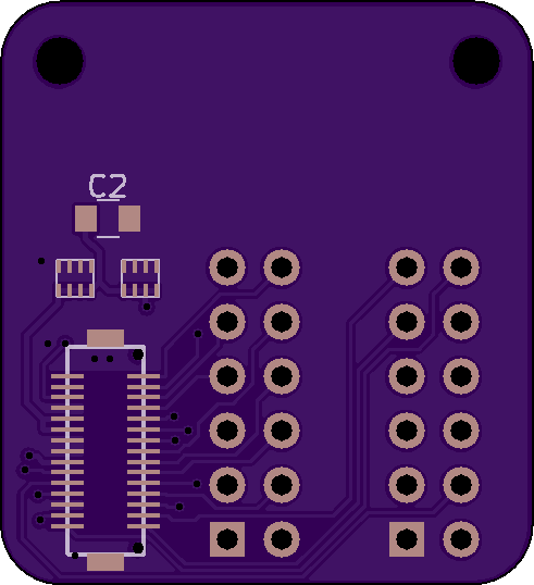
4 layer board of 0.98 x 2.65 inches (24.9 x 67.2 mm)
Uploaded:
December 30, 2018
Shared:
December 30, 2018
Total Price:
$25.90
r2-Backplane
This is a backplane PCB for Digitabulum containing the power-management block and associated support circuits.
Intended usage
This PCB, combined with a Compute board, and a …
Show full description
r2-Backplane
This is a backplane PCB for Digitabulum containing the power-management block and associated support circuits.
Intended usage
This PCB, combined with a Compute board, and a …
Show full description
Digitabulum-r2-Compute-WROOM32U
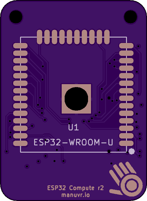
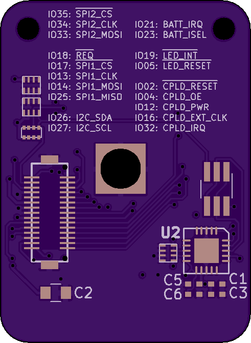
4 layer board of 0.98 x 1.34 inches (24.9 x 34.0 mm)
Uploaded:
December 30, 2018
Shared:
December 30, 2018
Total Price:
$13.10
Compute-WROOM32
This is one possible compute PCB to be used with Digitabulum-r2.
Intended usage
This PCB, combined with a backplane, and a Digitabulum-r2 board (plu…
Show full description
Compute-WROOM32
This is one possible compute PCB to be used with Digitabulum-r2.
Intended usage
This PCB, combined with a backplane, and a Digitabulum-r2 board (plu…
Show full description
Digitabulum Dev Backplane
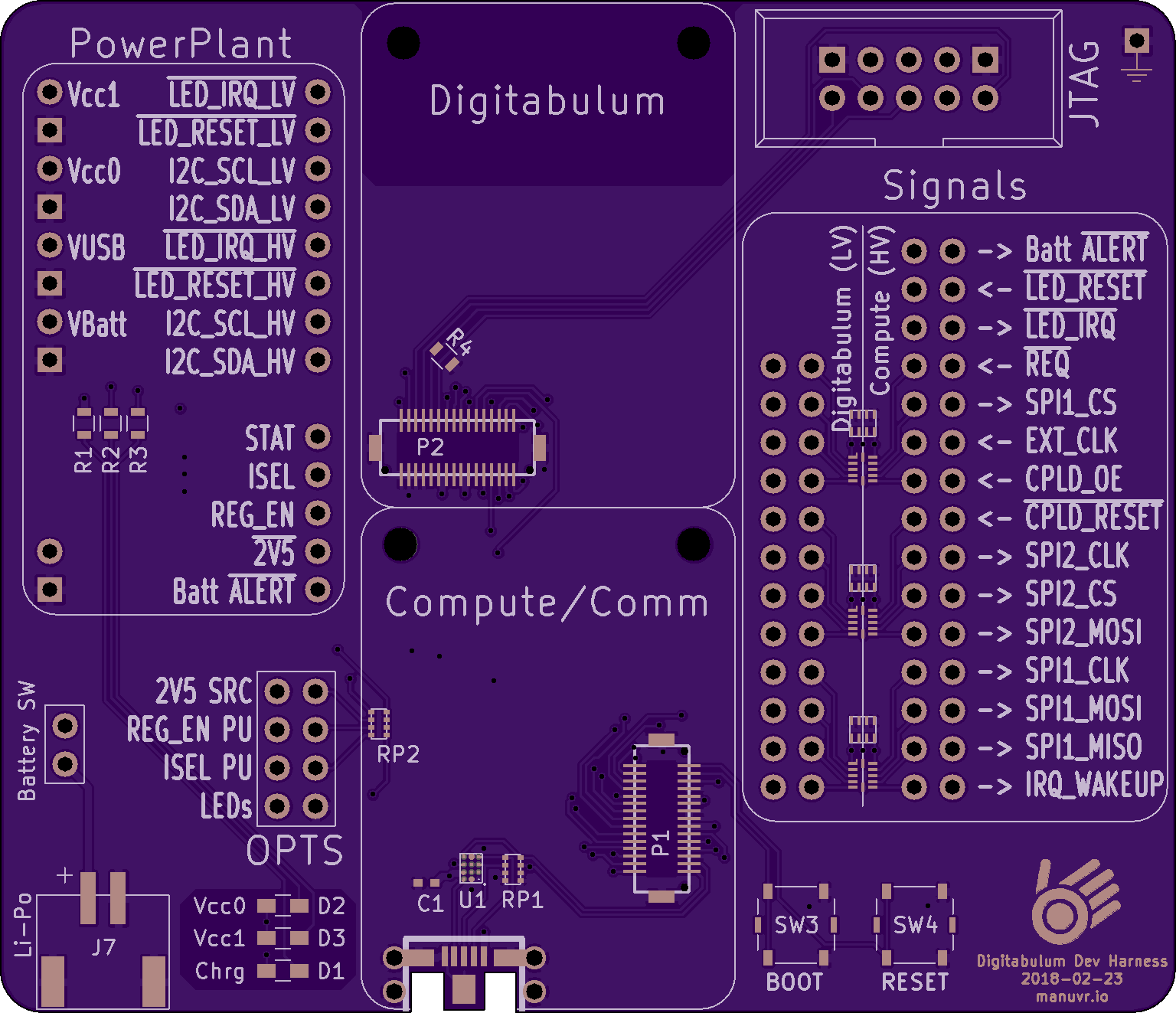
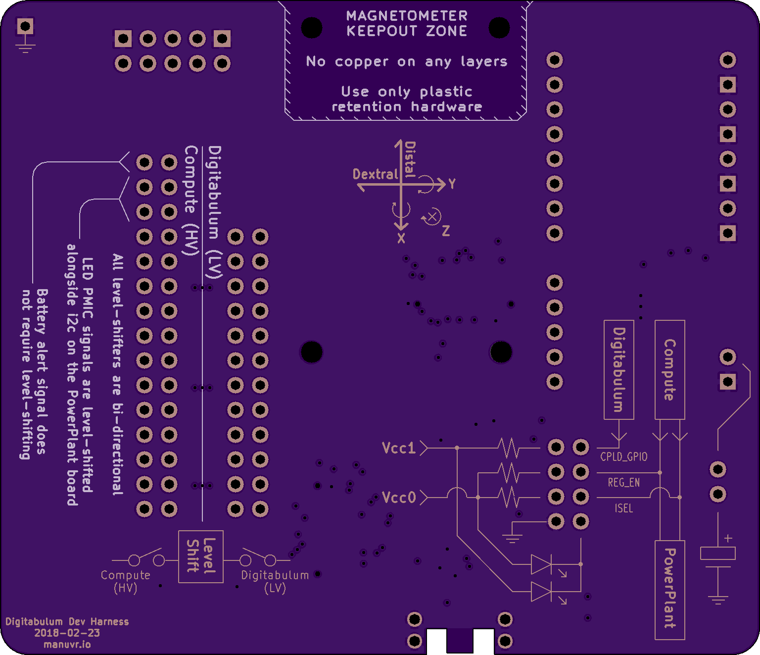
4 layer board of 3.07 x 2.65 inches (78.0 x 67.2 mm)
Uploaded:
February 26, 2018
Shared:
February 26, 2018
Total Price:
$81.30
This is a backplane PCB for Digitabulum. When combined with the PowerPlant, it has the same schematic as the r2-Backplane.
Intended usage
This b…
Show full description
This is a backplane PCB for Digitabulum. When combined with the PowerPlant, it has the same schematic as the r2-Backplane.
Intended usage
This b…
Show full description
Digitabulum-PowerPlant

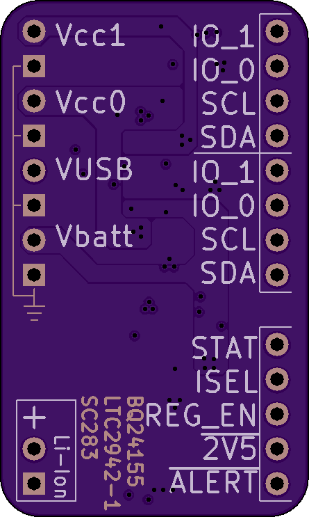
4 layer board of 0.89 x 1.49 inches (22.6 x 37.8 mm)
Uploaded:
August 22, 2017
Shared:
August 22, 2017
Total Price:
$13.20
This is the power-management block of Manuvr's motion-capture glove. It has been broken out as a module for testing and re-use.
Intended usage
A software-mediated single-cell li-ion batt…
Show full description
This is the power-management block of Manuvr's motion-capture glove. It has been broken out as a module for testing and re-use.
Intended usage
A software-mediated single-cell li-ion batt…
Show full description
Digitabulum-Compute-Template
4 layer board of 0.98 x 1.08 inches (24.9 x 27.3 mm)
Uploaded:
June 17, 2017
Shared:
June 17, 2017
Total Price:
$10.50
Provides a breakout to the compute/comm PCB connector on the r2-Backplane. It is also useful as a template for a custom Compute PCB.
Intended usage
This project has two purposes:
1) T…
Show full description
Provides a breakout to the compute/comm PCB connector on the r2-Backplane. It is also useful as a template for a custom Compute PCB.
Intended usage
This project has two purposes:
1) T…
Show full description
- ← Previous
- 1
- 2
- 3
- 4
- Next →
