Shared Projects by bwshockley
Shared Projects by bwshockley
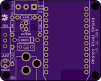
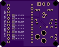
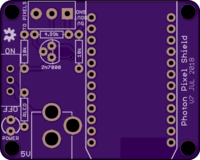
Photon Pixel Shield v5
2 layer board of 1.76 x 1.41 inches (44.7 x 35.8 mm)
Uploaded:
July 12, 2018
Shared:
July 12, 2018
Total Price:
$12.35
Photon Pixel Shield
The photon pixel shield is a small board for interfacing between a particle.io photon and some WS2812 based LED strips. Specifically, this board was made to drive Neopixel strips.
Power Require…
Photon Pixel Shield
The photon pixel shield is a small board for interfacing between a particle.io photon and some WS2812 based LED strips. Specifically, this board was made to drive Neopixel strips.
Power Requirements - Diode and Fuse Sizing
The board takes in 5V only and is used to power the photon and the pixel strip. Please note that current requirements are mostly driven by the number of LEDs being driven. Each WS2812 LED uses an estimate of 20mA, which can add up quickly.
50 Neopixels: 1A 100 Neopixels: 2A
You will need to pick your own diode and fuse. Since these devices are through hole, physical sizing isn’t as much of a concern for finding the right part - mostly the current/voltage ratings. I found fuses and diodes up to 3A easily fit. Find a Diode with a low forward voltage (less than 0.5V)
Digital Control
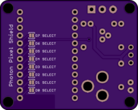
The WS2812 based LED strips can be controlled via the photon and the Neopixel library from Adafruit built by technobly. No digital pin is selected by default on the board. Pin D2 is the default in the library. To use the default connect the solder jumper for D2 on the back of the board. Otherwise, you may select almost any digital pin in both software on through the jumper on the board.
BOM
The majority of the BOM, which as of 12-JUL-18, can be found on Mouser.com for around $3.50. You will need to pick a diode and re-settable fuse as noted above.
Power LED
A simple 3mm power LED is required if you wish to have a power indicator. The resistor marked RLED on the board is for the LED. Populate with an appropriate resistor value for the LED chosen. You can use this calculate for sizing the resistor.
Show full description
Photon Pixel Shield
The photon pixel shield is a small board for interfacing between a particle.io photon and some WS2812 based LED strips. Specifically, this board was made to drive Neopixel strips.
Power Require…
Photon Pixel Shield
The photon pixel shield is a small board for interfacing between a particle.io photon and some WS2812 based LED strips. Specifically, this board was made to drive Neopixel strips.
Power Requirements - Diode and Fuse Sizing
The board takes in 5V only and is used to power the photon and the pixel strip. Please note that current requirements are mostly driven by the number of LEDs being driven. Each WS2812 LED uses an estimate of 20mA, which can add up quickly.
50 Neopixels: 1A 100 Neopixels: 2A
You will need to pick your own diode and fuse. Since these devices are through hole, physical sizing isn’t as much of a concern for finding the right part - mostly the current/voltage ratings. I found fuses and diodes up to 3A easily fit. Find a Diode with a low forward voltage (less than 0.5V)
Digital Control
The WS2812 based LED strips can be controlled via the photon and the Neopixel library from Adafruit built by technobly. No digital pin is selected by default on the board. Pin D2 is the default in the library. To use the default connect the solder jumper for D2 on the back of the board. Otherwise, you may select almost any digital pin in both software on through the jumper on the board.
BOM
The majority of the BOM, which as of 12-JUL-18, can be found on Mouser.com for around $3.50. You will need to pick a diode and re-settable fuse as noted above.
Power LED
A simple 3mm power LED is required if you wish to have a power indicator. The resistor marked RLED on the board is for the LED. Populate with an appropriate resistor value for the LED chosen. You can use this calculate for sizing the resistor.
Show full description
-
Actions
- Order Board
- Download
- Permalink
- Embed link
Ordering shared project
Hey there! Before ordering, make sure you have all the info you need to complete and use this design. This usually means a component list, and sometimes additional information such as assembly notes, source code, or usage guides.Since this is a project designed by a community member, it may contain design errors that prevent it from working as intended. OSH Park cannot place any guarantees about the functionality or correctness of the design.
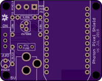
Photon Pixel Shield v6 No Diode
2 layer board of 1.76 x 1.41 inches (44.7 x 35.8 mm)
Uploaded:
July 12, 2018
Shared:
July 12, 2018
Total Price:
$12.35
Photon Pixel Shield - No Diode Version
The photon pixel shield is a small board for interfacing between a particle.io photon and some WS2812 based LED strips. Specifically, this board was made to drive Neopixel strip…
Photon Pixel Shield - No Diode Version
The photon pixel shield is a small board for interfacing between a particle.io photon and some WS2812 based LED strips. Specifically, this board was made to drive Neopixel strips.
Power Requirements - Fuse Sizing
The board takes in 5V only and is used to power the photon and the pixel strip. Please note that current requirements are mostly driven by the number of LEDs being driven. Each WS2812 LED uses an estimate of 20mA, which can add up quickly.
50 Neopixels: 1A 100 Neopixels: 2A
You will need to pick your own re-settable fuse. Since this device is through hole, physical sizing isn’t as much of a concern for finding the right part - mostly the current/voltage ratings. I found fuses up to 3A easily fit.
Digital Control
The WS2812 based LED strips can be controlled via the photon and the Neopixel library from Adafruit built by technobly. No digital pin is selected by default on the board. Pin D2 is the default in the library. To use the default connect the solder jumper for D2 on the back of the board. Otherwise, you may select almost any digital pin in both software on through the jumper on the board.
BOM
The majority of the BOM, which as of 12-JUL-18, can be found on Mouser.com for around $3.50. You will need to pick a re-settable fuse as noted above.
Power LED
A simple 3mm power LED is required if you wish to have a power indicator. The resistor marked RLED on the board is for the LED. Populate with an appropriate resistor value for the LED chosen. You can use this calculate for sizing the resistor.
Show full description
Photon Pixel Shield - No Diode Version
The photon pixel shield is a small board for interfacing between a particle.io photon and some WS2812 based LED strips. Specifically, this board was made to drive Neopixel strip…
Photon Pixel Shield - No Diode Version
The photon pixel shield is a small board for interfacing between a particle.io photon and some WS2812 based LED strips. Specifically, this board was made to drive Neopixel strips.
Power Requirements - Fuse Sizing
The board takes in 5V only and is used to power the photon and the pixel strip. Please note that current requirements are mostly driven by the number of LEDs being driven. Each WS2812 LED uses an estimate of 20mA, which can add up quickly.
50 Neopixels: 1A 100 Neopixels: 2A
You will need to pick your own re-settable fuse. Since this device is through hole, physical sizing isn’t as much of a concern for finding the right part - mostly the current/voltage ratings. I found fuses up to 3A easily fit.
Digital Control
The WS2812 based LED strips can be controlled via the photon and the Neopixel library from Adafruit built by technobly. No digital pin is selected by default on the board. Pin D2 is the default in the library. To use the default connect the solder jumper for D2 on the back of the board. Otherwise, you may select almost any digital pin in both software on through the jumper on the board.
BOM
The majority of the BOM, which as of 12-JUL-18, can be found on Mouser.com for around $3.50. You will need to pick a re-settable fuse as noted above.
Power LED
A simple 3mm power LED is required if you wish to have a power indicator. The resistor marked RLED on the board is for the LED. Populate with an appropriate resistor value for the LED chosen. You can use this calculate for sizing the resistor.
Show full description
-
Actions
- Order Board
- Download
- Permalink
- Embed link
Ordering shared project
Hey there! Before ordering, make sure you have all the info you need to complete and use this design. This usually means a component list, and sometimes additional information such as assembly notes, source code, or usage guides.Since this is a project designed by a community member, it may contain design errors that prevent it from working as intended. OSH Park cannot place any guarantees about the functionality or correctness of the design.
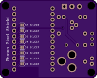
Photon Pixel Shield v7 No Diode and No Fuse
2 layer board of 1.76 x 1.41 inches (44.7 x 35.8 mm)
Uploaded:
July 12, 2018
Shared:
July 12, 2018
Total Price:
$12.35
Photon Pixel Shield - No Diode and No Fuse Version
The photon pixel shield is a small board for interfacing between a particle.io photon and some WS2812 based LED strips. Specifically, this board was made to drive [Neopixel](https://www.adafruit.com/categor…
Photon Pixel Shield - No Diode and No Fuse Version
The photon pixel shield is a small board for interfacing between a particle.io photon and some WS2812 based LED strips. Specifically, this board was made to drive Neopixel strips.
Power Requirements
The board takes in 5V only and is used to power the photon and the pixel strip. Please note that current requirements are mostly driven by the number of LEDs being driven. Each WS2812 LED uses an estimate of 20mA, which can add up quickly.
50 Neopixels: 1A 100 Neopixels: 2A
This board version has no fuse or diode, so the only power requirement consideration is your power supply.
Digital Control
The WS2812 based LED strips can be controlled via the photon and the Neopixel library from Adafruit built by technobly. No digital pin is selected by default on the board. Pin D2 is the default in the library. To use the default connect the solder jumper for D2 on the back of the board. Otherwise, you may select almost any digital pin in both software on through the jumper on the board.
BOM
The majority of the BOM, which as of 12-JUL-18, can be found on Mouser.com for around $3.50.
Power LED
A simple 3mm power LED is required if you wish to have a power indicator. The resistor marked RLED on the board is for the LED. Populate with an appropriate resistor value for the LED chosen. You can use this calculate for sizing the resistor.
Show full description
Photon Pixel Shield - No Diode and No Fuse Version
The photon pixel shield is a small board for interfacing between a particle.io photon and some WS2812 based LED strips. Specifically, this board was made to drive [Neopixel](https://www.adafruit.com/categor…
Photon Pixel Shield - No Diode and No Fuse Version
The photon pixel shield is a small board for interfacing between a particle.io photon and some WS2812 based LED strips. Specifically, this board was made to drive Neopixel strips.
Power Requirements
The board takes in 5V only and is used to power the photon and the pixel strip. Please note that current requirements are mostly driven by the number of LEDs being driven. Each WS2812 LED uses an estimate of 20mA, which can add up quickly.
50 Neopixels: 1A 100 Neopixels: 2A
This board version has no fuse or diode, so the only power requirement consideration is your power supply.
Digital Control
The WS2812 based LED strips can be controlled via the photon and the Neopixel library from Adafruit built by technobly. No digital pin is selected by default on the board. Pin D2 is the default in the library. To use the default connect the solder jumper for D2 on the back of the board. Otherwise, you may select almost any digital pin in both software on through the jumper on the board.
BOM
The majority of the BOM, which as of 12-JUL-18, can be found on Mouser.com for around $3.50.
Power LED
A simple 3mm power LED is required if you wish to have a power indicator. The resistor marked RLED on the board is for the LED. Populate with an appropriate resistor value for the LED chosen. You can use this calculate for sizing the resistor.
Show full description
-
Actions
- Order Board
- Download
- Permalink
- Embed link
Ordering shared project
Hey there! Before ordering, make sure you have all the info you need to complete and use this design. This usually means a component list, and sometimes additional information such as assembly notes, source code, or usage guides.Since this is a project designed by a community member, it may contain design errors that prevent it from working as intended. OSH Park cannot place any guarantees about the functionality or correctness of the design.
Mini SAM 2017-01-016
4 layer board of 0.95 x 1.55 inches (24.2 x 39.3 mm)
Uploaded:
March 08, 2017
Shared:
November 03, 2017
Total Price:
$14.70
*Note this version updates version 2017-001-015 with slightly smaller SWD programming header holes for POGO PIN programming. Please use 015 if you plan to solder in a 2x5 header per the BOM.
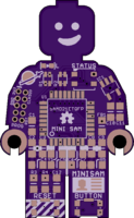
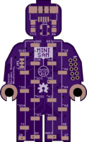
This is a LEGO Minifigure sized development board using an Atmel SAMD21E 32-Bit ARM chip. I basically…
*Note this version updates version 2017-001-015 with slightly smaller SWD programming header holes for POGO PIN programming. Please use 015 if you plan to solder in a 2x5 header per the BOM.
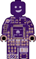
This is a LEGO Minifigure sized development board using an Atmel SAMD21E 32-Bit ARM chip. I basically followed the recommended layout/setup from the SAMD21 spec sheets.
Included on Mini SAM is a WS2812B LED pad connected to PIN 27, a 0603 LED connected to PIN 15, a reset button with support components per the datasheet, and a generic button that is active HIGH on PIN 28. The 0603 LED is connected in series with a 1Kohm resistor, part of R1, and care should be taken when selecting an 0603 LED such that at a supply of 3.3V, no more than 5mA is required.
Programming port is a standard10-pin SWD for ARM based processors, which is a 2x5 1.27mm pitch connector. The SWD line is pulled up with a 1Kohm resistor, part of R1. In the BOM, either purchase the 2x5 straight pin connector OR the 2x5 POGO connector and do not populate board.
The SDA/SCL pins are pulled high with 4.7KOhm resistors, R2, per SDA/SCL recommendations.
The voltage regulator is an AP2112K-3.3V which is rated at 600mA at 3.3V. Plenty of current for the SAMD21E and a few other accessories such as the WS2812B.
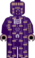
This version has SMT layout for two single row 2.54mm pitch headers on the back. It is designed to be protoboard friendly and when populated the headers are the same width as a DIL package (7.62mm or .3") and span the center of a protoboard.
PINs 27 and 28 are not connected to headers - due to lack of space - but instead have two pads near the bottom of the board. PIN 27 is connected to the on-board WS2812B. PIN 28 is connected to the on-board BUTTON.
The Analog Reference (PIN AREF) - has a pair of decoupling/filtering capacitors.
The micro-USB connector has an RC filter between the case/shield of the connector and GND. If R6 and C13 are left un-populated the case/shield is an open circuit - which is the next best option. Also included is space for a PRTR5V0U2X ESD protection circuit on USB Data lines. This may also be left un-populated and USB will function normally.
I have put together a sample BOM via Mouser.com which I’m including here. It can be used as a reference. Optional, but highly recommended components: SW2812B 3535 LED, 0603 LED, SW2 (BUTTON), R4, R5, R6, C13, and PRTR5V0U2X. R1 is for the 0603 LED and SWCLK - If not populating the 0603 LED this may be left un-populated as well and programming via SWD should still work as I’ve seen other boards without the 1Kohm resistor on SWCLK. R2 is the 4.7Kohm pull-up resistor pair for SDA/SCL. Many breakout boards using chips that run off SDA/SCL typically come with the 4.7Kohm pull-up resistor pair included - as such it may not be needed on Mini SAM - but it is included for ease of future components. Please review the schematic for additional details and be aware that the BOM on Mouser.com may be out of date. The SW2812B is not in the Mouser BOM - due to lack of parts.
I would suggest not purchasing the 2.54mm pitch SMT male headers from Mouser, as you can find this much cheaper elsewhere. The best I could find on Mouser is (2) 5-Pin and (2) 6-Pin headers. Mini SAM requires (2) 11-PIN headers. I suggest buying breakaway headers in 25-50 PIN lengths.
Arduino FIRMWARE/BOOTLOADER is complete, but I’m still testing all functions. So far all PINs work in digital setup and all analog PINs work accordingly. ANALOG and special function pins (MOSI, SDA, SCK, etc) can be accessed in Arduino by their name.
Please check my Github for the latest design files and bootloade/firmware.
More details can be found on Github
Show full description
*Note this version updates version 2017-001-015 with slightly smaller SWD programming header holes for POGO PIN programming. Please use 015 if you plan to solder in a 2x5 header per the BOM.
This is a LEGO Minifigure sized development board using an Atmel SAMD21E 32-Bit ARM chip. I basically…
*Note this version updates version 2017-001-015 with slightly smaller SWD programming header holes for POGO PIN programming. Please use 015 if you plan to solder in a 2x5 header per the BOM.
This is a LEGO Minifigure sized development board using an Atmel SAMD21E 32-Bit ARM chip. I basically followed the recommended layout/setup from the SAMD21 spec sheets.
Included on Mini SAM is a WS2812B LED pad connected to PIN 27, a 0603 LED connected to PIN 15, a reset button with support components per the datasheet, and a generic button that is active HIGH on PIN 28. The 0603 LED is connected in series with a 1Kohm resistor, part of R1, and care should be taken when selecting an 0603 LED such that at a supply of 3.3V, no more than 5mA is required.
Programming port is a standard10-pin SWD for ARM based processors, which is a 2x5 1.27mm pitch connector. The SWD line is pulled up with a 1Kohm resistor, part of R1. In the BOM, either purchase the 2x5 straight pin connector OR the 2x5 POGO connector and do not populate board.
The SDA/SCL pins are pulled high with 4.7KOhm resistors, R2, per SDA/SCL recommendations.
The voltage regulator is an AP2112K-3.3V which is rated at 600mA at 3.3V. Plenty of current for the SAMD21E and a few other accessories such as the WS2812B.
This version has SMT layout for two single row 2.54mm pitch headers on the back. It is designed to be protoboard friendly and when populated the headers are the same width as a DIL package (7.62mm or .3") and span the center of a protoboard.
PINs 27 and 28 are not connected to headers - due to lack of space - but instead have two pads near the bottom of the board. PIN 27 is connected to the on-board WS2812B. PIN 28 is connected to the on-board BUTTON.
The Analog Reference (PIN AREF) - has a pair of decoupling/filtering capacitors.
The micro-USB connector has an RC filter between the case/shield of the connector and GND. If R6 and C13 are left un-populated the case/shield is an open circuit - which is the next best option. Also included is space for a PRTR5V0U2X ESD protection circuit on USB Data lines. This may also be left un-populated and USB will function normally.
I have put together a sample BOM via Mouser.com which I’m including here. It can be used as a reference. Optional, but highly recommended components: SW2812B 3535 LED, 0603 LED, SW2 (BUTTON), R4, R5, R6, C13, and PRTR5V0U2X. R1 is for the 0603 LED and SWCLK - If not populating the 0603 LED this may be left un-populated as well and programming via SWD should still work as I’ve seen other boards without the 1Kohm resistor on SWCLK. R2 is the 4.7Kohm pull-up resistor pair for SDA/SCL. Many breakout boards using chips that run off SDA/SCL typically come with the 4.7Kohm pull-up resistor pair included - as such it may not be needed on Mini SAM - but it is included for ease of future components. Please review the schematic for additional details and be aware that the BOM on Mouser.com may be out of date. The SW2812B is not in the Mouser BOM - due to lack of parts.
I would suggest not purchasing the 2.54mm pitch SMT male headers from Mouser, as you can find this much cheaper elsewhere. The best I could find on Mouser is (2) 5-Pin and (2) 6-Pin headers. Mini SAM requires (2) 11-PIN headers. I suggest buying breakaway headers in 25-50 PIN lengths.
Arduino FIRMWARE/BOOTLOADER is complete, but I’m still testing all functions. So far all PINs work in digital setup and all analog PINs work accordingly. ANALOG and special function pins (MOSI, SDA, SCK, etc) can be accessed in Arduino by their name.
Please check my Github for the latest design files and bootloade/firmware.
More details can be found on Github
Show full description
-
Actions
- Order Board
- Download
- Permalink
- Embed link
Ordering shared project
Hey there! Before ordering, make sure you have all the info you need to complete and use this design. This usually means a component list, and sometimes additional information such as assembly notes, source code, or usage guides.Since this is a project designed by a community member, it may contain design errors that prevent it from working as intended. OSH Park cannot place any guarantees about the functionality or correctness of the design.
Mini SAM 2017-01-015
4 layer board of 0.95 x 1.55 inches (24.2 x 39.3 mm)
Uploaded:
February 24, 2017
Shared:
February 24, 2017
Total Price:
$14.70
*Note this version updates version 2017/001-015 with a fix for the I2C disconnect jumper.
This is a LEGO Minifigure sized development board using an Atmel SAMD21E 32-Bit ARM chip. I basically followed the recommended layout/setup from the SAMD21 spec sheets.
Included on Mini SAM is a WS281…
*Note this version updates version 2017/001-015 with a fix for the I2C disconnect jumper.
This is a LEGO Minifigure sized development board using an Atmel SAMD21E 32-Bit ARM chip. I basically followed the recommended layout/setup from the SAMD21 spec sheets.
Included on Mini SAM is a WS2812B LED pad connected to PIN 27, a 0603 LED connected to PIN 15, a reset button with support components per the datasheet, and a generic button that is active HIGH on PIN 28. The 0603 LED is connected in series with a 1Kohm resistor, part of R1, and care should be taken when selecting an 0603 LED such that at a supply of 3.3V, no more than 5mA is required.
Programming port is a standard10-pin SWD for ARM based processors, which is a 2x5 1.27mm pitch connector. The SWD line is pulled up with a 1Kohm resistor, part of R1. In the BOM, either purchase the 2x5 straight pin connector OR the 2x5 POGO connector and do not populate board.
The SDA/SCL pins are pulled high with 4.7KOhm resistors, R2, per SDA/SCL recommendations.
The voltage regulator is an AP2112K-3.3V which is rated at 600mA at 3.3V. Plenty of current for the SAMD21E and a few other accessories such as the WS2812B.
This version has SMT layout for two single row 2.54mm pitch headers on the back. It is designed to be protoboard friendly and when populated the headers are the same width as a DIL package (7.62mm or .3") and span the center of a protoboard.
PINs 27 and 28 are not connected to headers - due to lack of space - but instead have two pads near the bottom of the board. PIN 27 is connected to the on-board WS2812B. PIN 28 is connected to the on-board BUTTON.
The Analog Reference (PIN AREF) - has a pair of decoupling/filtering capacitors.
The micro-USB connector has an RC filter between the case/shield of the connector and GND. If R6 and C13 are left un-populated the case/shield is an open circuit - which is the next best option. Also included is space for a PRTR5V0U2X ESD protection circuit on USB Data lines. This may also be left un-populated and USB will function normally.
I have put together a sample BOM via Mouser.com which I’m including here. It can be used as a reference. Optional, but highly recommended components: SW2812B 3535 LED, 0603 LED, SW2 (BUTTON), R4, R5, R6, C13, and PRTR5V0U2X. R1 is for the 0603 LED and SWCLK - If not populating the 0603 LED this may be left un-populated as well and programming via SWD should still work as I’ve seen other boards without the 1Kohm resistor on SWCLK. R2 is the 4.7Kohm pull-up resistor pair for SDA/SCL. Many breakout boards using chips that run off SDA/SCL typically come with the 4.7Kohm pull-up resistor pair included - as such it may not be needed on Mini SAM - but it is included for ease of future components. Please review the schematic for additional details and be aware that the BOM on Mouser.com may be out of date. The SW2812B is not in the Mouser BOM - due to lack of parts.
I would suggest not purchasing the 2.54mm pitch SMT male headers from Mouser, as you can find this much cheaper elsewhere. The best I could find on Mouser is (2) 5-Pin and (2) 6-Pin headers. Mini SAM requires (2) 11-PIN headers. I suggest buying breakaway headers in 25-50 PIN lengths.
Arduino FIRMWARE/BOOTLOADER is complete, but I’m still testing all functions. So far all PINs work in digital setup and all analog PINs work accordingly. ANALOG and special function pins (MOSI, SDA, SCK, etc) can be accessed in Arduino by their name.
Please check my Github for the latest design files and bootloade/firmware.
More details can be found on Github
Show full description
*Note this version updates version 2017/001-015 with a fix for the I2C disconnect jumper.
This is a LEGO Minifigure sized development board using an Atmel SAMD21E 32-Bit ARM chip. I basically followed the recommended layout/setup from the SAMD21 spec sheets.
Included on Mini SAM is a WS281…
*Note this version updates version 2017/001-015 with a fix for the I2C disconnect jumper.
This is a LEGO Minifigure sized development board using an Atmel SAMD21E 32-Bit ARM chip. I basically followed the recommended layout/setup from the SAMD21 spec sheets.
Included on Mini SAM is a WS2812B LED pad connected to PIN 27, a 0603 LED connected to PIN 15, a reset button with support components per the datasheet, and a generic button that is active HIGH on PIN 28. The 0603 LED is connected in series with a 1Kohm resistor, part of R1, and care should be taken when selecting an 0603 LED such that at a supply of 3.3V, no more than 5mA is required.
Programming port is a standard10-pin SWD for ARM based processors, which is a 2x5 1.27mm pitch connector. The SWD line is pulled up with a 1Kohm resistor, part of R1. In the BOM, either purchase the 2x5 straight pin connector OR the 2x5 POGO connector and do not populate board.
The SDA/SCL pins are pulled high with 4.7KOhm resistors, R2, per SDA/SCL recommendations.
The voltage regulator is an AP2112K-3.3V which is rated at 600mA at 3.3V. Plenty of current for the SAMD21E and a few other accessories such as the WS2812B.
This version has SMT layout for two single row 2.54mm pitch headers on the back. It is designed to be protoboard friendly and when populated the headers are the same width as a DIL package (7.62mm or .3") and span the center of a protoboard.
PINs 27 and 28 are not connected to headers - due to lack of space - but instead have two pads near the bottom of the board. PIN 27 is connected to the on-board WS2812B. PIN 28 is connected to the on-board BUTTON.
The Analog Reference (PIN AREF) - has a pair of decoupling/filtering capacitors.
The micro-USB connector has an RC filter between the case/shield of the connector and GND. If R6 and C13 are left un-populated the case/shield is an open circuit - which is the next best option. Also included is space for a PRTR5V0U2X ESD protection circuit on USB Data lines. This may also be left un-populated and USB will function normally.
I have put together a sample BOM via Mouser.com which I’m including here. It can be used as a reference. Optional, but highly recommended components: SW2812B 3535 LED, 0603 LED, SW2 (BUTTON), R4, R5, R6, C13, and PRTR5V0U2X. R1 is for the 0603 LED and SWCLK - If not populating the 0603 LED this may be left un-populated as well and programming via SWD should still work as I’ve seen other boards without the 1Kohm resistor on SWCLK. R2 is the 4.7Kohm pull-up resistor pair for SDA/SCL. Many breakout boards using chips that run off SDA/SCL typically come with the 4.7Kohm pull-up resistor pair included - as such it may not be needed on Mini SAM - but it is included for ease of future components. Please review the schematic for additional details and be aware that the BOM on Mouser.com may be out of date. The SW2812B is not in the Mouser BOM - due to lack of parts.
I would suggest not purchasing the 2.54mm pitch SMT male headers from Mouser, as you can find this much cheaper elsewhere. The best I could find on Mouser is (2) 5-Pin and (2) 6-Pin headers. Mini SAM requires (2) 11-PIN headers. I suggest buying breakaway headers in 25-50 PIN lengths.
Arduino FIRMWARE/BOOTLOADER is complete, but I’m still testing all functions. So far all PINs work in digital setup and all analog PINs work accordingly. ANALOG and special function pins (MOSI, SDA, SCK, etc) can be accessed in Arduino by their name.
Please check my Github for the latest design files and bootloade/firmware.
More details can be found on Github
Show full description
-
Actions
- Order Board
- Download
- Permalink
- Embed link
Ordering shared project
Hey there! Before ordering, make sure you have all the info you need to complete and use this design. This usually means a component list, and sometimes additional information such as assembly notes, source code, or usage guides.Since this is a project designed by a community member, it may contain design errors that prevent it from working as intended. OSH Park cannot place any guarantees about the functionality or correctness of the design.
- SERVICES
- Upload Your File
- Prototypes
- HELP
- Support
- If you can't find what you're looking for, please contact us at [email protected]
- CONNECT
- Shared Projects
- Log in / Sign up
