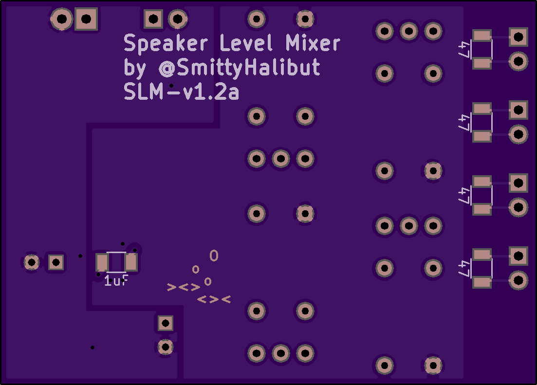
Speaker Level Mixer. Sorry for the crummy notes. Poke me on Twitter: @SmittyHalibut if you have any questions.
Summary:
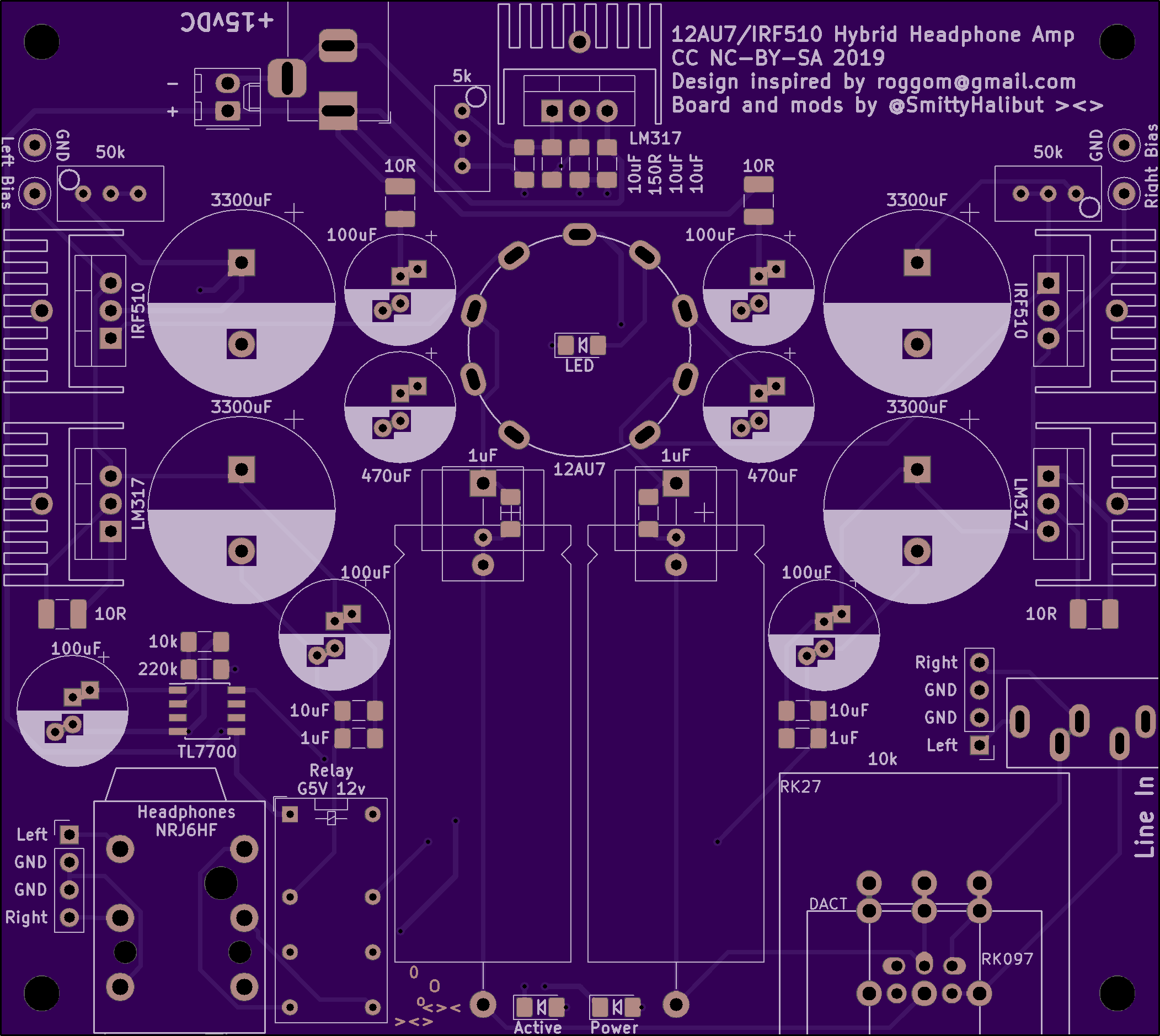
It's designed to take speaker outputs from mobile radios, like Amateur Radio VHF/UHF mobiles or HTs, isolate them from each other, convert them down to line level, mix …
Speaker Level Mixer. Sorry for the crummy notes. Poke me on Twitter: @SmittyHalibut if you have any questions.
Summary:
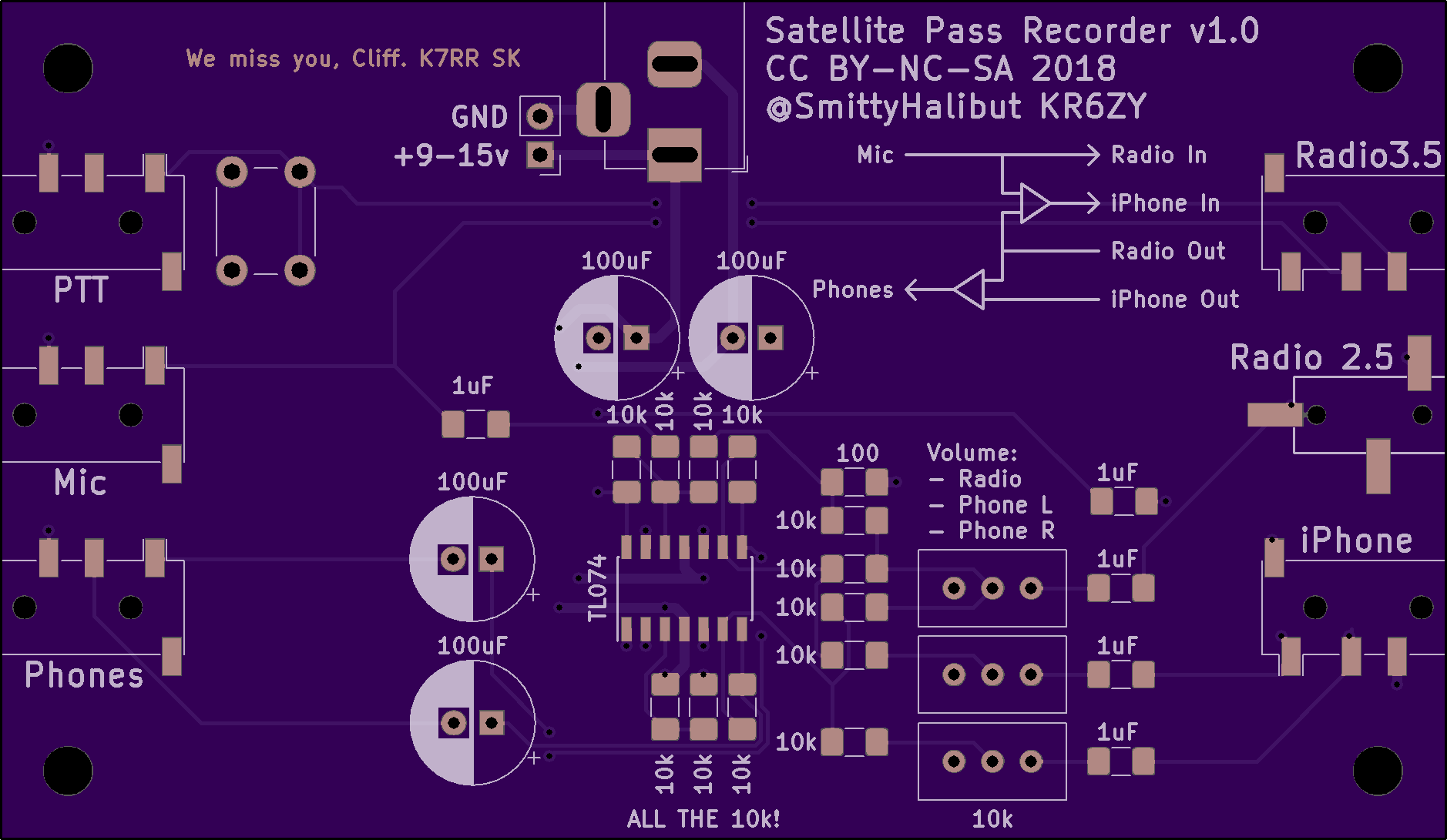
It’s designed to take speaker outputs from mobile radios, like Amateur Radio VHF/UHF mobiles or HTs, isolate them from each other, convert them down to line level, mix them together, and present the mix as a line level output to an external power amplifier (not part of this board) to be sent to a single speaker with audio from several radios mixed together.
The inputs are transformer isolated, so it will work with ground referenced single ended speaker outputs, push-pull speaker outputs, and speakers on completely different ground systems without creating ground loops.
The output of this board is LINE LEVEL not speaker level. You need to provide your own power amp before sending to a speaker.
Parts:
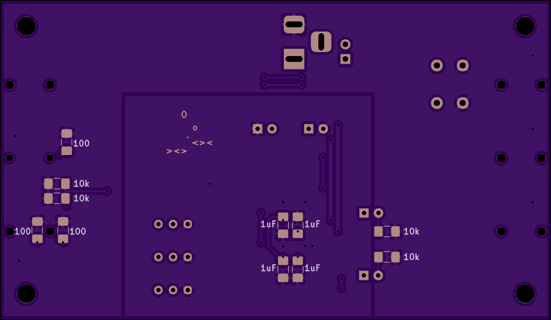
- All SMT parts are 1206 size. Values as marked on the board, except as noted below in the Tweaks section.
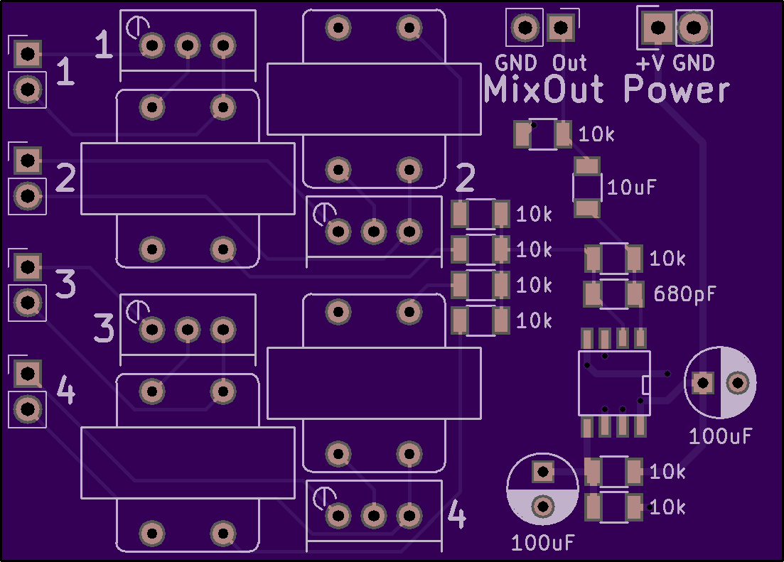
- The SOIC-8 is a dual op-amp of your choice, such as an TL072 or similar. Just about any dual op-amp will work here, so long as it’s stable at unity gain and can handle the voltage you plan to supply it with.
- Trim pots are 1k.
- I think I laid them out backwards, so clockwise is volume down, anti-clockwise is volume up. I think. Maybe. They might be right, I don’t remember. Sorry.
- Transformers are standard 1:1 audio transformers, often described as 600:600. If you have 6 pin transformers, just clip the center lead, which is a center tap that we aren’t using.
- Headers are standard .100" (2.54mm) headers. There’s enough space for you to use Molex KK series locking headers if you want, but the outline was meant for Dupont headers.
Power:
The only components that care about the power are the op-amp and capacitors. Assuming you’re running this on “13.8vDC” (read: something between 11v and 15v), make sure your op-amp can handle that. We generate our own false ground/bias voltage at Vcc/2.
Make sure your capacitors can handle that voltage too, especially the electrolytics. They need at least a 1.4x safety margin, but I usually go with 2x. So if you’re doing 13.8vDC, I’d use AT LEAST 25v caps, preferably 35v or higher caps.
This is all line level, not speaker level, so it won’t consume much power at all, probably 1s or 10s of mA. MAYBE 100mA if you try to drive a speaker directly or something. It won’t be much.
Tweaks:
- The impedance your source sees is dominated by the 47ohm resistors on the bottom of the board. These can be adjusted if you want. Speakers are typically 8 to 16ohms, but most amps don’t need a full load to work cleanly. If you adjust this too low, your source might start distorting, and you’ll be dissipating a lot of heat in this mixer. Too high, and you might get more noise than you want (but you’d have to go REALLY high for that.) I’ve found that 47 to 100 ohms works fine in my use cases.
- If you get too much RF on this line. you can shunt it by putting a .1uF cap in parallel with the load resistor on the bottom. Just stack them on top of each other. .1uF is a safe bet, but the exact value of that cap depends on the load resistor, and your desired cut-off frequency. f=1/(2piR*C) A .1uF cap will work from 8 ohms (200kHz) to 100 ohms (16kHz).
- The values on the board give you a unity (voltage) gain amp. The trim pots on the inputs are used to bring the speaker level voltage down to a reasonable line level.
- BUT: That might saturate your audio transformers resulting in really bad and weird sounding distortions. If it does, you need to drop the levels even lower to get through the transformer undistorted.
- In this case, you can get that voltage back by increasing the gain on the op-amp by increasing the value of the 10k resistor right next to the 680pF capacitor. (So many 10ks!) Get 2x gain by increasing it to 20k. 4.7x gain by increasing it to 47k, etc. (This is the feedback resistor in a standard inverting amplifier.)
- You also must decrease the value of the 680pF capacitor by the same amount you increase the resistor. Ish. It doesn’t need to be perfect. This is our favorite RC filter equation again: f=1/(2piRC). This is a low-pass filter, so we’re looking for a frequency at least above 4kHz for communications gear. 10k680pF is about 23kHz. If you increase the resistor by 2x, dropping the cap to 470pF results in a 17kHz cut-off, which is probably still fine.
- tl,dr: If you need to adjust the gain, do the math and pick an appropriate cap for your desired frequency response.