This driver has an input range of 1.8V to 5.5V (so 1 cell LiIon or 2-3 1.2V-1.5V cells), and can supply an LED with a voltage between 1.2V and 5.5V. Maximum output current depends on the input and output voltage, but it can be calculated with a few formulas in the TPS63020 datasheet. **Keep in mi…
This driver has an input range of 1.8V to 5.5V (so 1 cell LiIon or 2-3 1.2V-1.5V cells), and can supply an LED with a voltage between 1.2V and 5.5V. Maximum output current depends on the input and output voltage, but it can be calculated with a few formulas in the TPS63020 datasheet. Keep in mind, this driver has no low voltage cutoff! You have to check your battery voltage regularly!
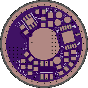
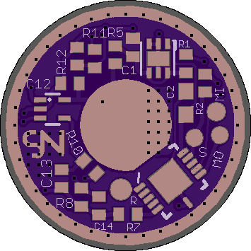
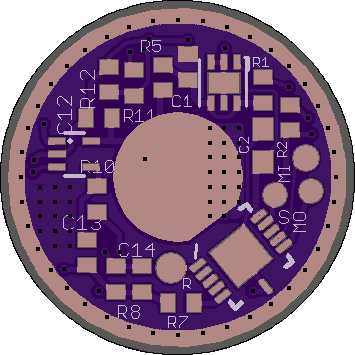
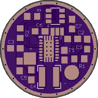
There are 3 pads on this board. The middle one has to be shorted with one of the outer ones. This for the power save mode. Short it with the outer pad marked with “D” to disable it (>150mA), or short it with the other pad marked “E” to enable it (<=150mA).
For a parts list, look here: Budget Light Forum
The current can be programmed via one resistor R3. When the parts listed are used the formula is:
Resistance (R3) = (2000×I)/(0.5V-0.02Ω×I)
(Current in A, Resistance in Ω)
Replace the “I” with your current you want. If you want a really low current , please change the current sense resistor (R1) to something bigger, and maybe change R2 as well.
To calculate current with your own parts, use this:
R3 = (R1×I×R2)/(0.5V-R1×I)
The OpAmp has to be chosen to fit the application. This depends on the input voltage range.
Some criterias to look out for:
Important: Look out how the input voltage offset changes over temperature and changes in supply voltage! This should be low.
First test by Lexel - it works!