4 layer board of 2.40 x 1.55 inches (61.0 x 39.4 mm)
Uploaded:
August 03, 2014
Shared:
August 03, 2014
Total Price:
$37.20
> # Alpha prototype stage. #
>This board uses an onboard Atmega328p to drive 6 N-Channel Mosfets with it's PWM pins.
>D2, D4, A0 and A1 are broken out along with GND 5v and Vin to a 2x5 header designed to run an external switch panel.
>ISCP pins are also broken out to allow in-situ progr…
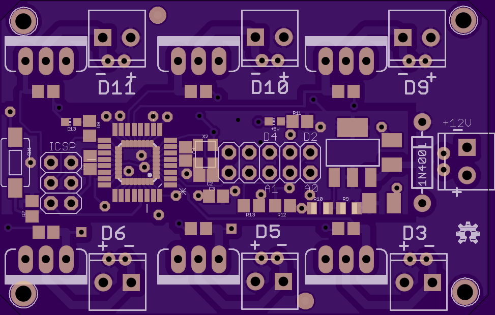
Alpha prototype stage.
This board uses an onboard Atmega328p to drive 6 N-Channel Mosfets with it’s PWM pins.
D2, D4, A0 and A1 are broken out along with GND 5v and Vin to a 2x5 header designed to run an external switch panel.
ISCP pins are also broken out to allow in-situ programming.
Heatsinking will be required for the Voltage regulator as it’s using an adjustable regulator to regulate from 12v down to 5v.
An LM1117MPX-5.0 fixed regulator can be used instead, leave R9 unpopulated and bridge R10 with a 0R link. C5 and C7 can be replaced with suitable Ceramics, though the datasheet suggests tantalum’s.
Heatsinking maybe required for the MOSFET’s depending on current draw, I suggest soldering them to the underside of the board and heatsinking them to your case, insulate them of course.
BOM
Show full description
> # Alpha prototype stage. #
>This board uses an onboard Atmega328p to drive 6 N-Channel Mosfets with it's PWM pins.
>D2, D4, A0 and A1 are broken out along with GND 5v and Vin to a 2x5 header designed to run an external switch panel.
>ISCP pins are also broken out to allow in-situ progr…
Alpha prototype stage.
This board uses an onboard Atmega328p to drive 6 N-Channel Mosfets with it’s PWM pins.
D2, D4, A0 and A1 are broken out along with GND 5v and Vin to a 2x5 header designed to run an external switch panel.
ISCP pins are also broken out to allow in-situ programming.
Heatsinking will be required for the Voltage regulator as it’s using an adjustable regulator to regulate from 12v down to 5v.
An LM1117MPX-5.0 fixed regulator can be used instead, leave R9 unpopulated and bridge R10 with a 0R link. C5 and C7 can be replaced with suitable Ceramics, though the datasheet suggests tantalum’s.
Heatsinking maybe required for the MOSFET’s depending on current draw, I suggest soldering them to the underside of the board and heatsinking them to your case, insulate them of course.
BOM
Show full description