JVS I/O Helper
author: Zarradeth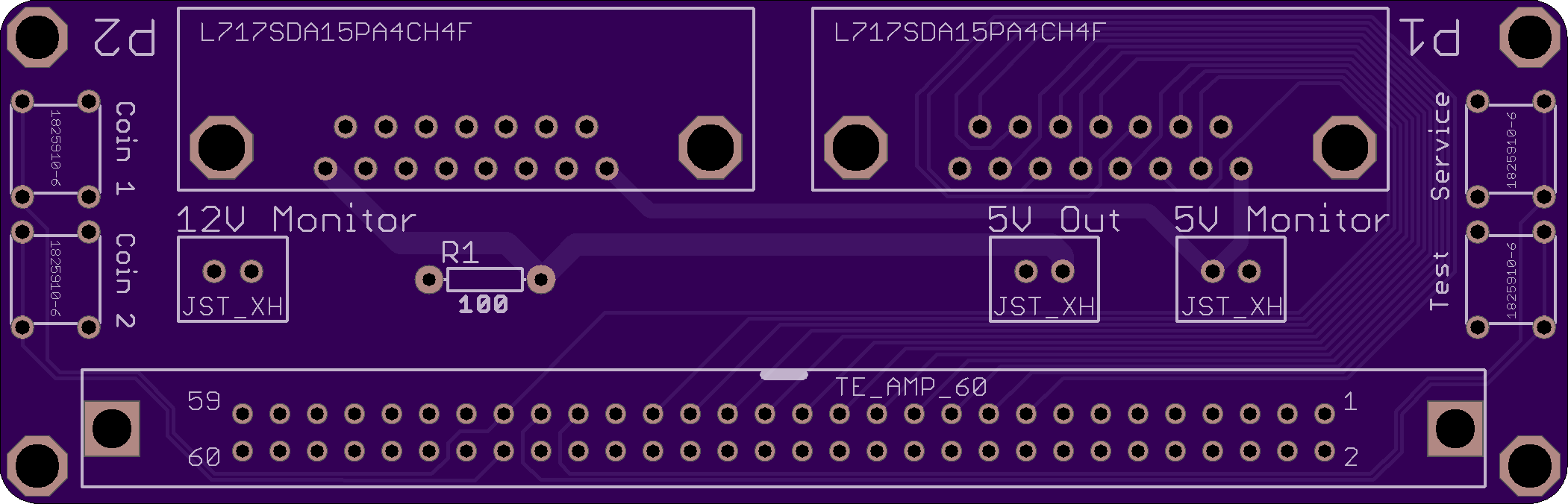
2 layer board of 4.20 x 1.35 inches (106.7 x 34.3 mm)
Uploaded:
July 23, 2017
Shared:
August 06, 2017
Total Price:
$28.35
(This version of the board has been tested with a 837-13551-92 and a Naomi system)
An adapter board for hooking up joysticks to a 837-13551-92 [JVS I/O Control Board Type 1], should also work with any I/O board that happens to share the same 60 pin Digital I/O connector with the same pinout (such as the 837-14572 [JVS I/O Control Board Type 3]).
This version of the board, with a flat ribbon cable, requires the cable runs over-top one of the boards (as the 60 pin connector faces the same direction as the 837-13551-92’s relative to the board). A version of this board with the same functionality, but a flipped 60 pin connector can be found at: http://oshpark.com/shared_projects/RW61aIl2
This board has plugs for a +5v and +12v monitor, they are not required. There is also a 2nd plug for a +5v out, intended for use with a modified USB cable to power a Pi. On the 2 pin connectors Pin 1 is output and Pin 2 is ground. The resistor on the board connects between +5v and the coin meter pins on the 60 pin connector to spoof the existence of coin meters for games that require it. The push buttons on the board are provided for ease of access to test/service/coin inputs, they do not need to be populated.
The board was designed to fit the following parts:
- All plugs are 2.5mm pitch, designed for JST XH plugs.
- The DB-15 connectors were designed for Amphenol’s L717SDA15PA4CH4F
- The push buttons were designed for TE Connectivity’s ALCOSWITCH Switches (1825910-6)
- The 60 pin connector was designed for TE Connectivity’s 60 Pin AMP connector (1-5102321-1)
The DB-15 plugs use the wiring that should be found on most Superguns: http://www.thesupergun.com/electrical/standard-supergun-controller-wiring-diagram/
In case the site cannot be reached the wiring is as follows:
- GND
- Button 6
- Coin
- Button 4
- Button 2
- Right
- Down
- +5v
- NC
- Button 5
- Start
- Button 3
- Button 1
- Left
- Up
